Display device, electronic device, and display device control method

一种显示装置、控制方法的技术,应用在静态指示器、仪器等方向,能够解决刷新率下降等问题,达到降低功耗、维持显示质量、抑制功耗的效果

Active Publication Date: 2016-06-08
SHARP KK
View PDF8 Cites 2 Cited by
  • Summary
  • Abstract
  • Description
  • Claims
  • Application Information

AI Technical Summary

Problems solved by technology

[0004] Patent Document 1 describes a liquid crystal display that, when there are no streaks in the image across a series of frames, judges that the frame has a feature that does not easily generate flicker, thereby reducing the refresh rate.

Method used


Image

  • Display device, electronic device, and display device control method
  • Display device, electronic device, and display device control method
  • Display device, electronic device, and display device control method

Examples


Embodiment approach 1

[0033] (Configuration of Display Device 1 )

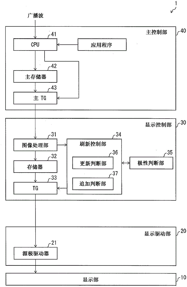
[0034] figure 1 It is a block diagram showing the configuration of the display device 1 of the present embodiment. The display device 1 includes a display unit 10 , a display drive unit 20 , a display control unit 30 , and a main control unit 40 . The display device 1 is a liquid crystal display device. In addition, the present invention is not limited to liquid crystal display devices, and can be applied to display devices that perform polarity inversion.

[0035] The display drive unit 20 is a COG driver mounted on a glass substrate of the display unit 10 in a COG (Chipon Glass: chip on glass) format, and drives the display unit 10 . The main control unit 40 is a control board including a control circuit formed on the board, and is mainly responsible for the control of the main side of the display device 1 (for the control of electronic equipment). The display control unit 30 is a control board provided independently of the ...

reference example 1

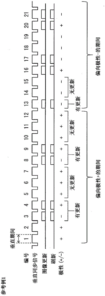
[0060] figure 2 It is a timing chart of image update and refresh of Reference Example 1 for comparison. exist figure 2 , the horizontal axis is time. exist figure 2 In , the vertical synchronization signal is a signal defining each vertical period, and here, for convenience, each vertical period is numbered. exist figure 2 In , the rectangle of "image update" or "refresh" indicates that there is image update or refresh in the vertical period, and "polarity" indicates the polarity of the pixel in the vertical period (the polarity of the data signal written to the pixel) .

[0061] In the display device of Reference Example 1, refreshing (writing data signals to pixels) is performed only in the vertical period in which the image is updated, and no refreshing is performed in the vertical period in which the image is not updated. Accordingly, power consumption during a period when no image update is performed can be reduced. In addition, in Reference Example 1, the pola...

reference example 2

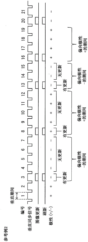
[0066] image 3 It is a timing chart of image update and refresh of Reference Example 2 for comparison. image 3 Each element in represents and figure 2 same meaning. image 3 shown in Reference Example 2 with figure 2 The reference example 1 shown differs in the timing of image update.

[0067] For example, when the image is updated as in Reference Example 2, the polarity is also reversed at the timing of the image update, so the period during which one polarity is biased is shorter than that of Reference Example 1. Therefore, in the case of Reference Example 2, the flicker is not easily seen by the user.

[0068] (Operation example 1)

[0069] In this embodiment, in order to solve the above-mentioned problem that the flicker is seen, an additional refresh is performed during the period when the image is not updated. The operation of the display device 1 of this embodiment will be described below.

[0070] Figure 4 It is a sequence diagram showing image update and ...


PUM


Abstract

An objective of the present invention is to implement a display device which consumes less power and carries out satisfactory display. A display device (1) according to an aspect of the present invention is provided with: a polarity determination unit (35) which determines whether a first polarity of a vertical drive interval immediately prior to a first interval wherein an image is not updated is the same as a second polarity of the most recent vertical idle interval prior to the vertical drive interval,and a refresh control unit (34) which disposes an additional vertical interval in the first interval if the first polarity and the second polarity are the same.

Description

technical field [0001] The present invention relates to a display device, an electronic device and a control method of the display device. Background technique [0002] In recent years, thin, lightweight, and low power consumption display devices typified by liquid crystal display devices have remarkably spread. Typical mounting forms of such a display device are, for example, a mobile phone, a smart phone, a notebook PC (Personal Computer: personal computer), and the like. In addition, it is expected that the development and popularization of electronic paper, which is a thinner display device, will also advance rapidly in the future. Under such circumstances, reducing power consumption has become a common problem in various display devices. [0003] In conventional CG (Continuous Grain: continuous grain) silicon TFT liquid crystal display panels, amorphous silicon TFT liquid crystal display panels, etc., it is necessary to refresh the screen at 60 Hz. Therefore, in orde...

Claims


Application Information

Patent Timeline
Patent Type & Authority Applications(China)
IPC IPC(8): G09G3/36G09G3/20
CPCG09G3/3614G09G3/3648G09G2320/0247G09G2320/0257G09G2330/021G09G2340/0435G09G3/2092G09G3/36
Inventor 渡边辰雄朝井淳毅前田健次
Owner SHARP KK
Why Eureka
Try Eureka