
Illuminating device

A lighting device and optical lens technology, which is applied in the direction of lighting devices, lighting device components, lighting and heating equipment, etc., can solve the problem that LED light sources are difficult to meet the needs, and achieve the effect of large lighting range

Inactive Publication Date: 2010-09-29
FOXSEMICON INTEGRATED TECHNOLOGY (SHANGHAI) INC +1
View PDF0 Cites 3 Cited by
  • Summary
  • Abstract
  • Description
  • Claims
  • Application Information

AI Technical Summary

Problems solved by technology

However, the LED light source is difficult to meet the occasions that require a larger lighting range

Method used


Image

  • Illuminating device
  • Illuminating device
  • Illuminating device

Examples


Embodiment Construction

[0015] The embodiments of the present invention will be further described in detail below in conjunction with the accompanying drawings.

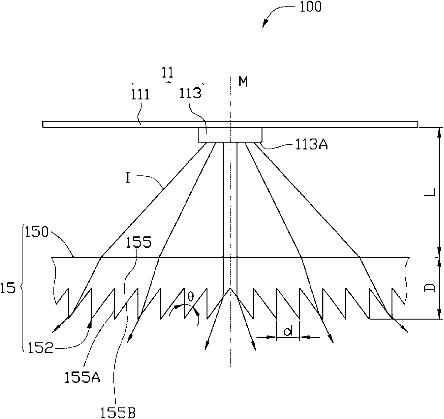
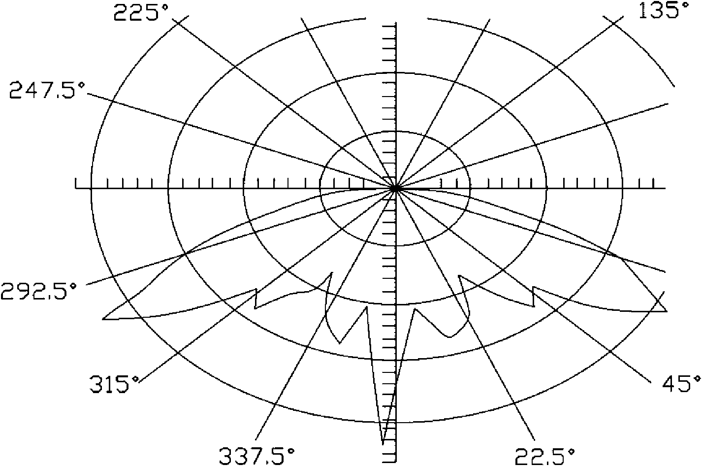
[0016] Please refer to figure 2 and image 3 , the first embodiment of the present invention provides a lighting device 100 , which includes: a light source module 11 and an optical lens 15 .

[0017] The light source module 11 includes a substrate 111 and a solid-state light source 113 installed on the substrate 111 . The substrate 111 can be a circuit board 111 , and the circuit board 111 can be connected to an external power source through the lines arranged on it, so as to supply power to the solid-state light source 113 . The solid-state light source 113 can be an LED chip or an LED, which has a central axis of symmetry M. As shown in FIG. When the solid-state light source 113 is an LED, it emits light I from its light-emitting surface 113A after it is energized to form a radial light field, and the light distribution curve of the ...


PUM


Abstract

The invention relates to an illuminating device, which comprises a solid light source with a central symmetry axis and an optical lens. The optical lens is arranged opposite to the solid light source and comprises an incident light surface and an emergent light surface opposite to the incident light surface, wherein the at least one of the incident light surface and the emergent light surface is provided with a plurality of first strip-shaped microstructures extended along a first direction; and the plurality of first strip-shaped microstructures are symmetrically arranged on the two sides of the central symmetry axis so as to expand the radiation range of ray in a second direction vertical to the first direction. The optical lens arranged in the illuminating device can enlarge the radiation range of the ray after emergence, so that a larger illuminating range is obtained.

Description

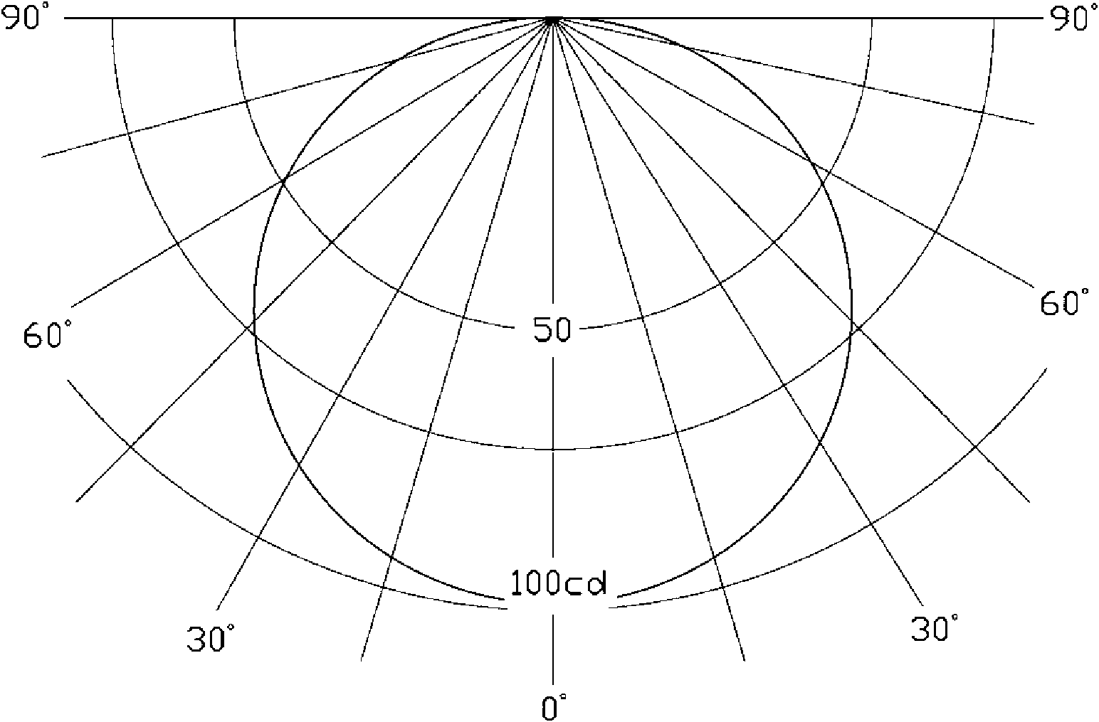
technical field [0001] The invention relates to an illuminating device, in particular to an illuminating device with a relatively large illuminating range. Background technique [0002] Light Emitting Diode (LED, Light Emitting Diode) has the advantages of high brightness, low operating voltage, low power consumption, easy to match with integrated circuits, simple driving, long life, etc. Therefore, it is widely used as an ideal light source in various lighting occasions For details, please refer to the article Thermal Considerations for LED Components in an Automotive Lamp published by Joseph Bielecki et al. on the 2007 IEEE, 23rd IEEE SEMI-THERM Symposium. [0003] In optics, light distribution curve is usually used to represent the distribution of light in space. For all kinds of existing light sources, such as LED light sources, they usually have approximately radial light distribution curves, such as figure 1 A light distribution curve with a Lambertian distribution i...

Claims


Application Information

Patent Timeline
Patent Type & Authority Applications(China)
IPC IPC(8): F21V5/04H01L33/00F21Y101/02
CPCF21V5/002G02B5/02G02B5/045F21Y2101/02F21Y2115/10F21V5/02
Inventor 韦安琪赖志铭
Owner FOXSEMICON INTEGRATED TECHNOLOGY (SHANGHAI) INC
Learn More