Compact, flexible CSP facility for continuous, semi-continuous and batch operation

A compact and semi-continuous technology, applied in the direction of metal processing equipment, workpiece surface treatment equipment, braking/tensioning devices, etc., can solve the problems of long extension length, quality reduction, unfavorable production operations of steel types, etc., and achieve good roll heat insulation and compact structure

Inactive Publication Date: 2010-09-29
SMS DEMAG AG
View PDF3 Cites 18 Cited by
  • Summary
  • Abstract
  • Description
  • Claims
  • Application Information

AI Technical Summary

Problems solved by technology

In continuous operation, production cannot be maintained during roll changes
If it is operated discontinuously, the plant is disadvantageous for most steel grades because of the resulting loss of quality
[0007] Furthermore, the extension lengths of these devices are generally very long, which leads to a rather high production cost factor

Method used


Image

  • Compact, flexible CSP facility for continuous, semi-continuous and batch operation
  • Compact, flexible CSP facility for continuous, semi-continuous and batch operation
  • Compact, flexible CSP facility for continuous, semi-continuous and batch operation

Examples


Embodiment Construction

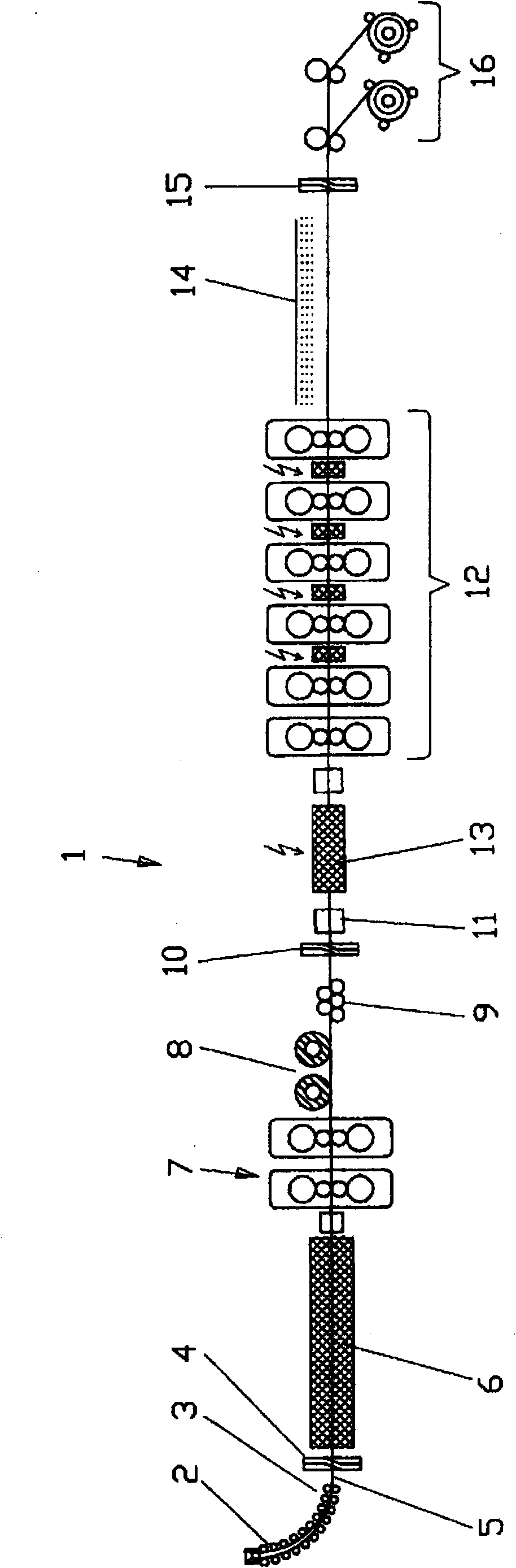
[0029] figure 1 A schematic diagram showing a flexible and compact CSP plant 1 for continuous operation, semi-continuous operation and intermittent operation. The plant 1 here has a continuous casting machine 2 with a continuous casting machine outlet 3 . After the continuous casting machine outlet 3, a shearing machine 4 is arranged, so that the cast strand 5 coming out of the continuous casting machine outlet 3 can be sheared. A furnace 6 , for example preferably a tunnel furnace, is located downstream of the shear 4 , which heats the strand 5 to the desired temperature. The furnace 6 is therefore located between the caster outlet 3 and the shear 4 on the one hand and the subsequent roughing train 7 on the other hand. exist figure 1 In the embodiment, the roughing group 7 includes double roughing stands. According to another inventive concept, however, the roughing train 7 can also have a single roughing stand or three roughing stands. In this exemplary embodiment, afte...


PUM


Abstract

The invention relates to a compact, flexible CSP facility (1,101,201,301,401) for continuous, semi-continuous and batch operation, comprising a casting machine, a roughing stand group (7,111,211) and a finishing stand group (12,118,218), wherein a coil store (8,113,213,501) which stores the rough strip or slab coming from the roughing stand is integrated in the roller table for batch or semi-continuous operation, wherein the coil store is deactivated in continuous operation. The coil store (8,113,213,501) is designed to hold an increased quantity of rough strips or slabs in such a way that two, three or more rough strips or slabs can be wound onto a coil to form jumbo coils.

Description

technical field [0001] The invention relates to a flexible and compact CSP plant for continuous, semi-continuous and intermittent operation, in particular according to the preamble of claim 1 . Background technique [0002] In CSP (Thin Slab Casting Direct Rolling Technology) plants, strip, as the name suggests, is generally produced in a continuous production process. This means that the continuous casting operation and the rolling operation take place almost one after the other. [0003] DE102006054932A1 discloses a CSP plant in which an induction heating furnace and a holding furnace are arranged between the continuous casting machine and the rolling mill train for maintaining or slightly raising the temperature of the thin slab, where the holding furnace and the induction The heating furnace is put into use, stops working or is controlled or adjusted according to the operation mode. [0004] EP0286862A1 discloses a continuous rolling process in which the continuous cas...

Claims


Application Information

Patent Timeline
Patent Type & Authority Applications(China)
IPC IPC(8): B21B1/46
CPCB21B39/006B21B45/008B21B2015/0057B21B39/084B21B2015/0064B21B1/466B21B1/46B21B45/004B21B1/463B21B13/22Y02P70/10
Inventor J·塞德尔P·苏道H·霍夫M·彼得斯
Owner SMS DEMAG AG
Why Eureka
Try Eureka