

High-pressure fuel pump
A high-pressure fuel pump, high-pressure technology, which is applied to fuel injection pumps, fuel injection devices, pumps, etc., can solve problems such as laborious installation, achieve good sealing, reduce high-pressure leakage, and reduce manufacturing costs.
- Summary
- Abstract
- Description
- Claims
- Application Information
AI Technical Summary
Problems solved by technology
Method used
Image

Examples
Embodiment Construction
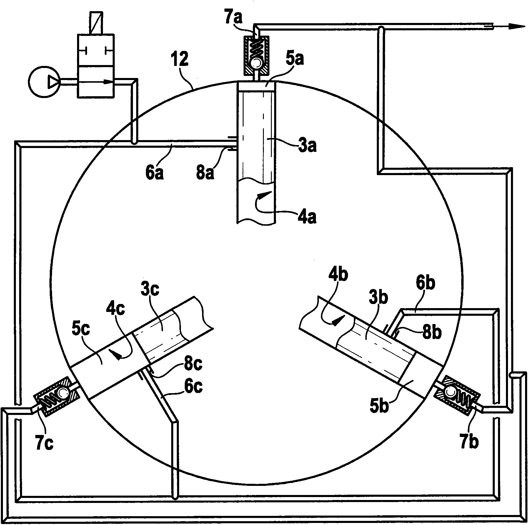
[0015] figure 1 A schematic diagram of a high-pressure fuel pump according to the invention is shown, which is provided with three pump pistons 3a, 3b and 3c. These pump pistons 3a-3c are respectively guided in piston guides 4a, 4b and 4c and are arranged at an angle equidistant from each other on the same circumferential line (12) around the pump camshaft not shown, through which the pump cam The polygonal configuration of the shaft collectively drives the pump pistons. A pressure chamber 5a, 5b and 5c is provided above each pump piston 3a-3c. These pressure chambers 5a-5c are in turn connected with low-pressure feed lines 6a, 6b and 6c respectively and with high-pressure connections 7a, 7b and 7c, which are connected to the feed holes 8a, 8b and 8c in the piston guides 4a-4c. form.
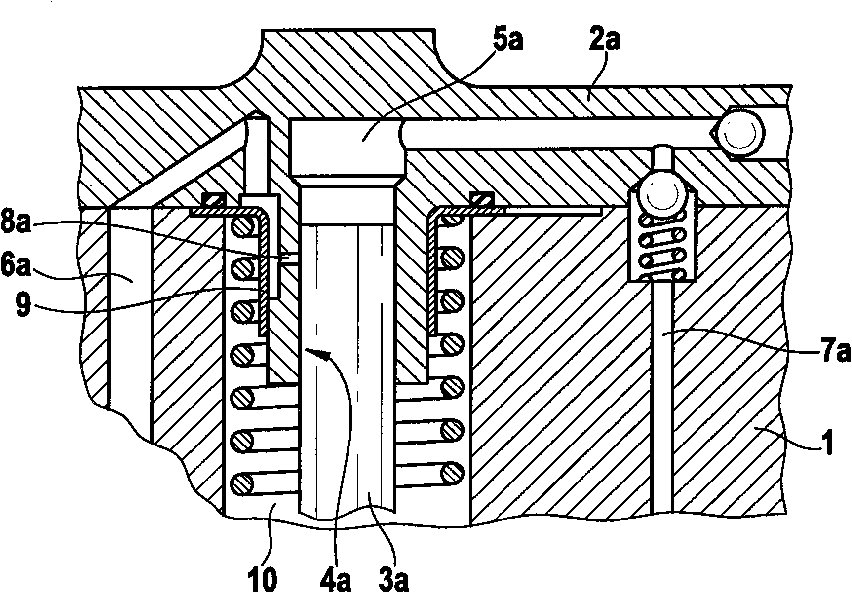
[0016] exist figure 2 A detailed sectional view of a pressure chamber 5a and a pump piston 3a can be seen in FIG. The pressure chamber 5a is supplied with fuel via the inlet opening 8a and...
PUM
 Abstract
Description
Claims
Application Information