

Composite vacuum pump
A technology of vacuum pump and pump casing, applied in the field of dry composite vacuum pump, can solve the problems of bulky, high energy consumption, huge pump body, etc., and achieve the effects of low energy consumption, large pumping speed and small size
- Summary
- Abstract
- Description
- Claims
- Application Information
AI Technical Summary
Problems solved by technology
Method used
Image

Examples
Embodiment 1
[0038] Embodiment 1: Vertical Siegbahn molecular pump
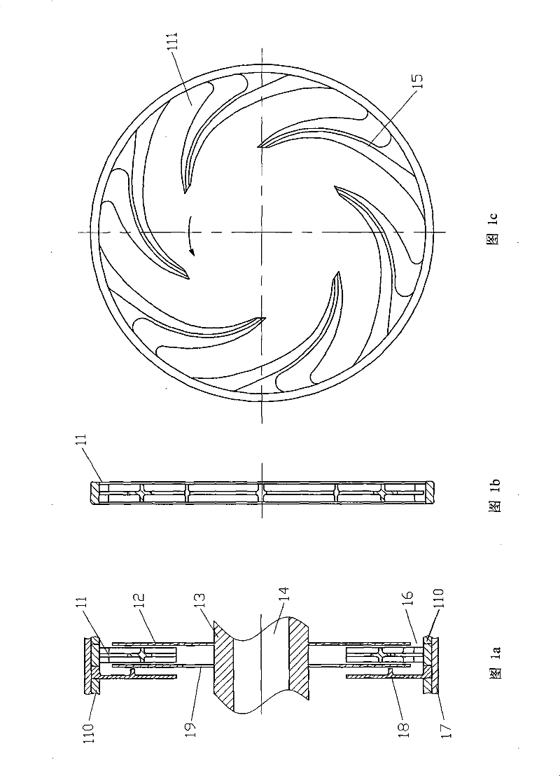
[0039] like Figure 1a , 1b As shown in and 1c, the vertical Siegbahn molecular pump includes a pump casing 17, a stationary wheel 11, a moving wheel 12, a dynamic seal 18, a rotor 13, a rotating shaft 14 and a spacer ring 110.
[0040] The stationary wheel 11, the dynamic seal 18 and the spacer ring 110 are fixed on the pump casing 17, the moving wheel 12 is fixed on the rotor 13, and an axial air inlet is arranged between the moving wheel 12 and the spacer ring 110. Mouth 16.
[0041] Specifically, the static wheel 11 is provided with several helical blades 15 (six in this embodiment), the cross-section of the blades 15 is cross-shaped, and the space between every two adjacent blades 15 forms an air extraction groove 111 , there is an opening in the middle of the bottom of the air extraction groove 111; the static wheel 11 adopts a single or multiple parallel combination to form a static wheel group; one side of the s...
Embodiment 2
[0044] Embodiment 2: Horizontal Siegbahn molecular pump
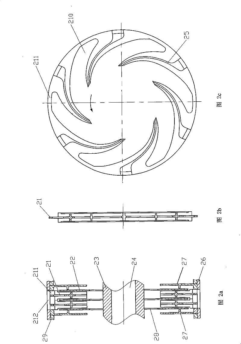
[0045] The basic structure of this embodiment is similar to Embodiment 1, as Figure 2a , 2b As shown in and 2c, the horizontal Siegbahn pump includes a pump casing 26, a stationary wheel 21, a dynamic seal 27, a spacer ring 29, a moving wheel 22, a rotor 23 and a shaft 24.
[0046] The static wheel 21, the dynamic seal 27 and the spacer ring 29 are fixed on the pump casing 26; the static wheel 21 adopts a single or multiple (shown as 2 in Fig. 2) parallel combination to form a static wheel group; Both sides of the static wheel 21 or the static wheel group are respectively provided with dynamic seals 27; the periphery of the static wheel 21 or the static wheel group is provided with a radial air inlet 211, and the pump casing 26 and the air inlet A gas channel 212 is provided at the position corresponding to the port 211 ; the moving wheel 22 is fixed on the rotor 23 ; the inner side of the moving wheel 22 is provided...
Embodiment 3
[0049] Embodiment 3, A-type Gaede traction molecular pump
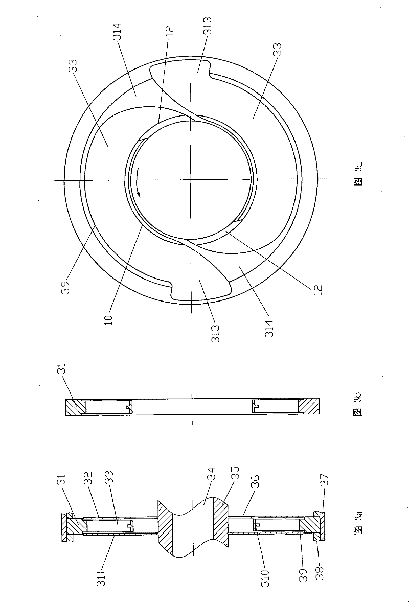
[0050] This example Figure 3a , 3b As shown in and 3c, the A-type Gaede molecular pump consists of a pump casing 37, a static wheel 31, a moving wheel 32, a moving wheel 311, a rotor 34, a rotating shaft 35 and a spacer ring 38.
[0051] The stationary wheel 31 and the spacer ring 38 are fixed on the pump casing 37 , the moving wheel 32 and the moving wheel 311 are fixed on the rotor 34 , and the inner side of the moving wheel 32 is provided with a gas channel 36 .
[0052] Specifically, the stationary wheel 31 is composed of a groove top 39, several (two shown in the figure) dynamic seals 314, an air extraction groove 33 and a groove bottom 310, forming an integral structure.
[0053] Both sides of described dynamic seal 314 are provided with air inlet 312 and exhaust port 313; Described air inlet 312 and exhaust port 313 are respectively positioned on groove bottom 310 and groove top 39; The section of described ...
PUM
 Abstract
Description
Claims
Application Information