Controllable high-pressure high-flow generating device and control method thereof

A technology of a generating device and a control method, which is applied to fluid pressure actuation devices, fluid pressure actuation system testing, mechanical equipment, etc., can solve problems such as high hardware cost, high system power, and uncontrollable output flow rate, and achieve extended The effect of flow output time, low cost and simple structure

Inactive Publication Date: 2010-10-06
CHINA COAL BEIJING COAL MINING MACHINERY +1
View PDF5 Cites 17 Cited by
  • Summary
  • Abstract
  • Description
  • Claims
  • Application Information

AI Technical Summary

Problems solved by technology

[0003] The main problems of the high-pressure and large-flow fluid source in the prior art are: 1) the output flow is uncontrollable; 2) the duration of the output flow is difficult to control; 3) the system has large power, high hardware cost, and low performance utilization efficiency of the accumulator

Method used


Image

  • Controllable high-pressure high-flow generating device and control method thereof
  • Controllable high-pressure high-flow generating device and control method thereof

Examples


specific Embodiment approach

[0011] The preferred embodiment of the controllable high pressure and large flow generating device of the present invention is:

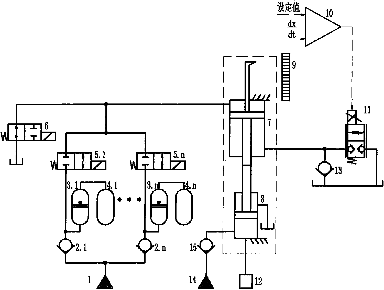
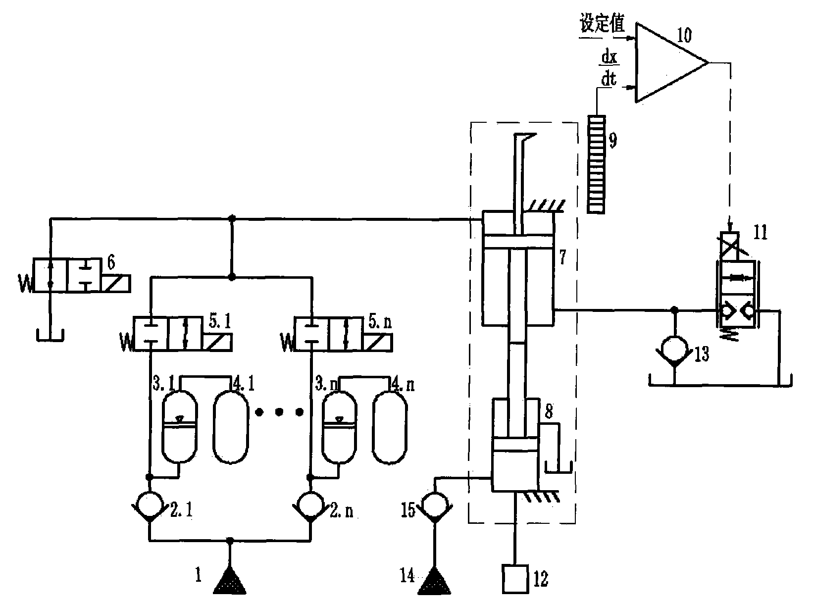
[0012] It includes a pump source, an accumulator group, a supercharger, a control valve group, and a flow detection and control device. The supercharger includes a low-pressure end hydraulic cylinder and a high-pressure end hydraulic cylinder with relatively fixed cylinders and piston rods facing each other. The pump source is connected to the rodless chamber of the hydraulic cylinder at the low pressure end through a plurality of pipelines connected in parallel, and each pipeline is provided with a separate accumulator and a two-position two normally closed directional control valve. The hydraulic cylinder is connected with a flow control device.

[0013] The accumulator set includes multiple piston accumulators and gas cylinders.

[0014] A one-way valve and a reversing valve are respectively arranged between the pump source and the accumulator o...

specific Embodiment

[0026] Specific examples, such as figure 1 shown, including:

[0027] 1. Hydraulic system, specifically including:

[0028] Pump source 1:

[0029] The pump source 1 can adopt different configurations and parameters according to the needs, and the illustration only shows the function symbol of the pump source;

[0030] Accumulator:

[0031] Various forms of accumulators can be used, such as figure 1 Shown is a better solution, using one or more piston accumulators (number: 3.1, 3.2...3.n) combined with one or more gas cylinders (number: 4.1, 4.2...4.n), the The method can make full use of the volume of the accumulator itself under a small pressure drop.

[0032] The combination of the accumulator in the specific embodiment is that a piston accumulator and a gas cylinder group form an accumulator, and the number of accumulators formed is two or more, connected in parallel, and multiple The accumulators output the flow sequentially by opening at the same time or relaying. ...


PUM


Abstract

The invention discloses a controllable high-pressure high-flow generating device and a control method thereof. The controllable high-pressure high-flow generating device comprises a pump source, an energy accumulator unit, a pressurizer, a control valve unit, a flow rate detecting and controlling device and the like, wherein the pressurizer comprises a low-pressure end hydraulic cylinder and a high-pressure end hydraulic cylinder which are provided with piston rods leaning against with each other; the pump source is connected with a non-rod cavity of the low-pressure end hydraulic cylinder bya plurality of pipelines which are connected in parallel; each pipeline is provided with an independent energy accumulator and a two-position and two-way normally-closed control valve; and the low-pressure end hydraulic cylinder is connected with the flow rate detecting and controlling device. A plurality of groups of energy accumulators are arranged for flexible combination, thus obtaining higher flow output by simultaneously outputting the flow; and the plurality of groups of energy accumulators can relay for prolonging the flow output time. A closed loop flow control loop can be used for controlling the output flow. The invention solves the problem of output flow control and maintaining time control of the existing high-pressure high-flow fluid source, and is simple in structure and low in cost.

Description

technical field [0001] The invention relates to a fluid power source providing high pressure and large flow for equipment such as a test bench, in particular to a controllable high pressure and large flow generating device and a control method thereof. Background technique [0002] Many occasions that require high-pressure and large-flow fluid sources, such as hydraulic support large-flow safety valve dynamic characteristics test bench, etc., are characterized by: 1) high pressure, up to 50MPa or more; 2) large flow, up to 1500L / min or more; 3 ) The power is large, up to hundreds of kilowatts or even more than one thousand kilowatts; 4) The duration is short, generally within a few seconds. In this case, an accumulator is usually used as the fluid source, and a supercharger is equipped to achieve high pressure. [0003] The main problems of the high-pressure and large-flow fluid source in the prior art are: 1) the output flow is uncontrollable; 2) the duration of the output...

Claims


Application Information

Patent Timeline
Patent Type & Authority Applications(China)
IPC IPC(8): F15B1/02F15B19/00
Inventor 郑本芳冯晓迪陈忠强芮丰李炳涛李晓丽
Owner CHINA COAL BEIJING COAL MINING MACHINERY
Why Eureka
Try Eureka