Equipment or system built-in test signal false-alarm filtering method based on empirical mode decomposition

An empirical mode decomposition and test signal technology, applied in complex mathematical operations, ships, ship parts, etc., can solve the problem of test signal filtering and eliminate false alarm signals, and achieve the effect of filtering false alarm signals

Inactive Publication Date: 2010-10-06
HARBIN INST OF TECH
View PDF1 Cites 14 Cited by
  • Summary
  • Abstract
  • Description
  • Claims
  • Application Information

AI Technical Summary

Problems solved by technology

[0005] The purpose of the present invention is to solve the problem that the existing method for filtering the test signal in the equipment or system cannot simultaneously eliminate the false alarm signal from the two aspects of frequency and amplitude, and provides a device or system based on empirical mode decomposition. False alarm filtering method for system built-in test signal

Method used


Image

  • Equipment or system built-in test signal false-alarm filtering method based on empirical mode decomposition
  • Equipment or system built-in test signal false-alarm filtering method based on empirical mode decomposition
  • Equipment or system built-in test signal false-alarm filtering method based on empirical mode decomposition

Examples


specific Embodiment approach 1

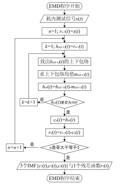
[0015] Specific implementation mode one: the following combination Figure 1 to Figure 2 This embodiment will be described.

[0016] Since the data processed by BIT is often non-stationary and nonlinear, we consider using Empirical Mode Decomposition (EMD), which has expertise in data processing in this area, to assist in filtering the BIT signal, thereby reducing the false alarm rate. the goal of.

[0017] EMD is an important constituent step of the Hilbert-Huang Transform (HHT), which was published by Dr. E Huang of the National Aeronautics and Space Administration (National Aeronautics and Space Administration, NASA) in 1998. Different from the traditional method that uses a fixed shape window as the boundary basis function, the basis function of EMD is an intrinsic mode function (IntrinsicModeFunction, IMF) extracted adaptively from the signal. It uses the change of the internal time scale of the signal to analyze the energy and frequency, and expands the signal into se...

specific Embodiment approach 2

[0055] Embodiment 2. The difference between this embodiment and Embodiment 1 is that T=0.25, and the others are the same as Embodiment 1.

specific Embodiment approach 3

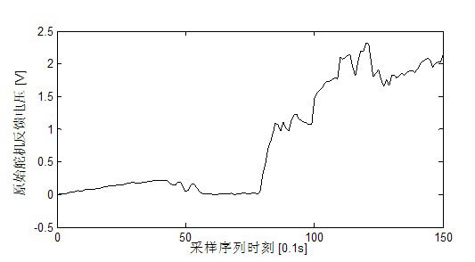
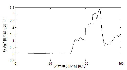
[0056] Specific implementation mode three: the following combination Figure 3 to Figure 20 Describe this embodiment, give a specific example, unmanned aerial vehicle is a kind of unmanned aerial vehicle, has lifting surface, can rely on autopilot and radio system control and do maneuver flight, it can complete aerial environment monitoring, forest Fire prevention, pesticide spraying, aerial reconnaissance and other tasks. In this embodiment, the signal is intercepted from the steering gear feedback voltage signal when the UAV performs a specified self-inspection task, and a section of original sampling data is selected respectively in the case of no fault and fault, as shown in image 3 with Figure 4 shown. from image 3 As shown in the no-fault situation, it can be seen that after the servo performs the self-inspection action, the voltage rises and tends to be stable, but due to its own disturbance and other reasons, there are many large-scale drops in the second half, w...


PUM


Abstract

The invention discloses an equipment or system built-in test signal false-alarm filtering method based on empirical mode decomposition, relates to a key processing technology for built-in test, and provides a filtering method for lowering the equipment or system built-in test signal false-alarm rate without the aid of any priori knowledge. The method comprises the following steps of: firstly, carrying out empirical mode decomposition on input built-in test signals and extracting 3 intrinsic mode function components and 1 residual error; secondly, carrying out self-adaptive attenuation processing on the extracted second-step intrinsic mode function component IMF2 obtain a decayed component DIMF2; and thirdly, carrying out signal superposition processing on the decayed component DIMF2 to obtain a filter signal of a built-in test signal and finish false-alarm filtering on the built-in test signal. Starting from a sampling signal per se, the invention overcomes the defect that the traditional filtering method can not simultaneously remove a false-alarm signal together from two respects of frequency and amplitude and is suitable for equipment or system built-in test signal false-alarm filtering.

Description

technical field [0001] The invention relates to a method for filtering false alarms of test signals in equipment or systems based on empirical mode decomposition, and belongs to the field of testing. Background technique [0002] Built-In Test (Built-InTest, BIT) is an automatic test capability provided by the device or system itself for fault detection, isolation or diagnosis. BIT is an important technical means to significantly improve system testing and diagnosis capabilities, and it is increasingly valued in the reliability, maintainability, and testability design of modern equipment. In the design, production and operation stages of equipment or system life cycle, testing has always been a very critical technology. First of all, in the design phase, the purpose of testing is to detect and point out the existence of design errors, so as to ensure that the produced products will work as intended. Next, during the production phase, the purpose of testing is to detect any...

Claims


Application Information

Patent Timeline
Patent Type & Authority Applications(China)
IPC IPC(8): G06F17/14B63B9/00
Inventor 沈毅张淼王强
Owner HARBIN INST OF TECH
Why Eureka
Try Eureka