Secondary optical lens used in focusing solar battery

A secondary optical lens and solar cell technology, applied in circuits, photovoltaic power generation, photovoltaic modules, etc., can solve problems such as poor photoelectric conversion efficiency of solar cell chips, uneven heating on the surface of solar cell chips, and poor reliability

Inactive Publication Date: 2010-10-06
河北英沃泰电子科技有限公司
View PDF7 Cites 1 Cited by
  • Summary
  • Abstract
  • Description
  • Claims
  • Application Information

AI Technical Summary

Problems solved by technology

[0005] The technical problem to be solved in the present invention is to reasonably design the shape of the secondary optical lens to solve the problem that the current secondary optical element has poor effect on improving the allowable sunlight incident angle, and the surface of the solar cell chip is heated unevenly due to the concentration of focused light spots. , resulting in poor photoelectric conversion efficiency and poor reliability of solar cell chips

Method used


Image

  • Secondary optical lens used in focusing solar battery
  • Secondary optical lens used in focusing solar battery
  • Secondary optical lens used in focusing solar battery

Examples


Embodiment 1

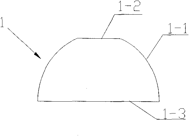
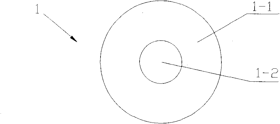
[0020] see figure 1 and figure 2 , a secondary optical lens 1 used in focusing solar cells, including a base body, the base body includes a convex arc surface 1-1 part of the light receiving surface, a plane 1-2 part of the light receiving surface and a light output surface 1-3. The light-receiving surface is mainly composed of a convex arc surface 1-1 and a plane 1-2 above the convex arc surface 1-1, the light-emitting surface 1-3 is a plane, and the plane 1-2 of the light-receiving surface and the light-emitting surface 1-3 Keep the space parallel to make the light spots converged on the solar cell chip more uniform. The convex arc surface 1-1 is preferably a spherical surface, the spherical surface is easy to process, the production process is simple, and it is easy for industrial automation production. The convex arc surface 1-1 can also be a convex arc surface of other shapes, such as a convex arc surface obtained by rotating a section of a convex parabola intercepted ...

Embodiment 2

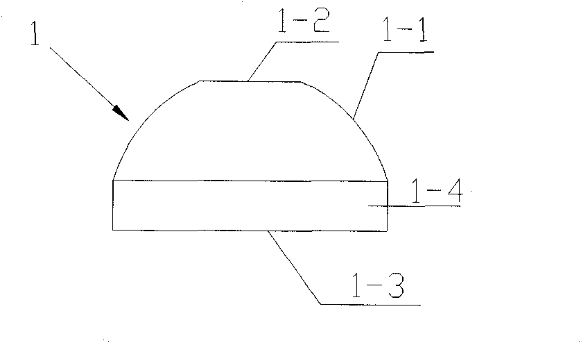
[0022] Referring to Fig. 3(a), a secondary optical lens 1 used in focusing solar cells differs from Embodiment 1 in that the matrix also includes a convex shape perpendicular to the light-emitting surface 1-3 and the light-receiving surface The first circumferential surface 1-4 intersected by the arc surface 1-1. The setting of the first circumferential surface 1-4 makes the design of the output spot shape more flexible. For example, the size of the light-receiving surface (1-1, 1-2) and the light-emitting surface 1-3 can be changed. The distance between the light-receiving surface (1-1, 1-2) and the light-emitting surface 1-3, or the distance between the light-receiving surface (1-1, 1-2) and the light-emitting surface 1-3 is constant Next, different concentrating effects and output spot shapes can be achieved by changing the curvature or shape of the convex arc surface 1-1 of the light-receiving surface.

Embodiment 3

[0024] Referring to Fig. 3 (b), a secondary optical lens 1 used in focusing solar cells differs from Embodiment 2 in that the substrate also includes a second lens with a diameter slightly larger than the first peripheral surface 1-4. Circumferential surface 1-5. Such a structural design can facilitate the installation of the secondary optical lens 1 .

[0025] In the above three embodiments, the smaller the refractive index of the secondary optical lens, the better, and the preferred refractive index of the present invention is less than 2.0. The smaller the refractive index, the less light reflected into the air by the secondary optical lens, and the greater the light energy incident on the solar cell chip. It is generally made of glass or quartz, and can also be made of other high-temperature-resistant and UV-resistant transparent materials with a refractive index less than 2.0.

[0026] Starting from the optical characteristics of the primary optical lens, the simulation...


PUM


Abstract

The invention provides a secondary optical lens used in a focusing solar battery, which is used for converging sunlight and coupling the converged light rays into a solar battery chip. The secondary optical lens comprises a basal body, wherein the basal body comprises a light receiving surface and a light-emitting surface; the light receiving surface mainly comprises a convex cambered surface and a plane positioned above the convex cambered surface; the light-emitting surface is a plane; and the plane above the convex cambered surface is parallel with the light-emitting surface. The secondary optical lens increases the light convergence energy, enlarges the allowed incidence angle of the sunlight, solves the problem in causing local overheating of the battery chip due to nonuniform light convergence to further reduce the photoelectric conversion efficiency of the battery chip, improves the stability of the battery chip for long-term operation, and simultaneously converges more sunlight to the surface of the battery chip so as to improve the power generation efficiency of a whole electro-optical system.

Description

technical field [0001] The invention relates to an optical lens, in particular to a non-imaging secondary optical lens for focusing solar cells. Background technique [0002] At present, a solar cell chip with a photoelectric conversion efficiency of more than 30% has been developed, but the chip is expensive. In order to reduce the area of ​​the chip and improve the efficiency of the chip, it is necessary to increase the concentration ratio of sunlight. In the case of concentrating light 500 times, the current photoelectric conversion efficiency can reach more than 38%. For an ideal and practical solar power generation system, in addition to solar cell chips with high photoelectric conversion efficiency, the system must also have high light concentration efficiency, because the photoelectric conversion efficiency of solar power generation components is equal to the photoelectric conversion efficiency of battery chips. Therefore, the most effective optical design structure ...

Claims


Application Information

Patent Timeline
Patent Type & Authority Applications(China)
IPC IPC(8): H01L31/0232H01L31/052H02S40/22
CPCY02E10/52Y02E10/50
Inventor 冯冠华钟玮
Owner 河北英沃泰电子科技有限公司
Why Eureka
Try Eureka