Secondary optical lens used in focusing solar battery
A secondary optical lens and solar cell technology, applied in circuits, photovoltaic power generation, photovoltaic modules, etc., can solve problems such as poor photoelectric conversion efficiency of solar cell chips, uneven heating of the surface of solar cell chips, and poor effects of sunlight incident angles.
- Summary
- Abstract
- Description
- Claims
- Application Information
AI Technical Summary
Problems solved by technology
Method used
Image
Examples
Embodiment 1
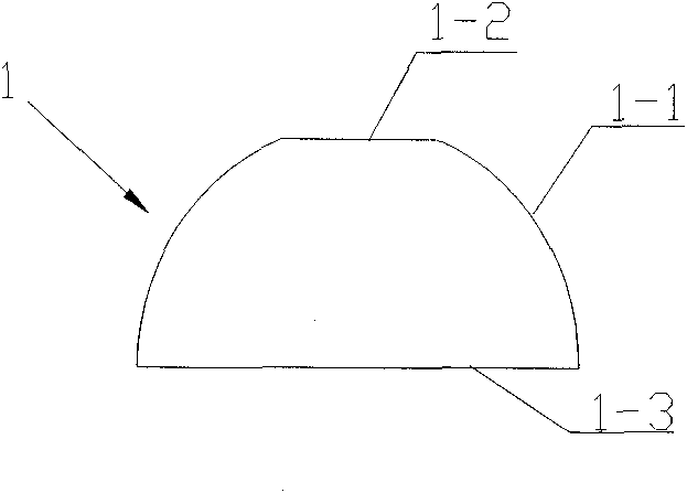
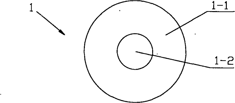
[0020] see figure 1 and figure 2 , a secondary optical lens 1 used in focusing solar cells, including a base body, the base body includes a convex arc surface 1-1 part of the light receiving surface, a plane 1-2 part of the light receiving surface and a light output surface 1-3. The light-receiving surface is mainly composed of a convex arc surface 1-1 and a plane 1-2 above the convex arc surface 1-1, the light-emitting surface 1-3 is a plane, and the plane 1-2 of the light-receiving surface and the light-emitting surface 1-3 Keep the space parallel to make the light spots converged on the solar cell chip more uniform. The convex arc surface 1-1 is preferably a spherical surface, the spherical surface is easy to process, the production process is simple, and it is easy for industrial automation production. The convex arc surface 1-1 can also be a convex arc surface of other shapes, such as a convex arc surface obtained by rotating a section of a convex parabola intercepted ...
Embodiment 2
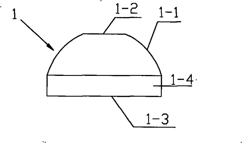
[0022] Referring to Figure 3(a), a secondary optical lens 1 used in focusing solar cells differs from Embodiment 1 in that the matrix also includes a convex shape perpendicular to the light-emitting surface 1-3 and the light-receiving surface The first circumferential surface 1-4 intersected by the arc surface 1-1. The setting of the first circumferential surface 1-4 makes the design of the output spot shape more flexible, for example, it can be changed under the condition that the size of the light receiving surface (1-1, 1-2) and the light emitting surface 1-3 are unchanged. The distance between the light-receiving surface (1-1, 1-2) and the light-emitting surface 1-3, or the distance between the light-receiving surface (1-1, 1-2) and the light-emitting surface 1-3 is constant Next, different concentrating effects and output spot shapes can be achieved by changing the curvature or shape of the convex arc surface 1-1 of the light-receiving surface.
Embodiment 3
[0024] Referring to Fig. 3 (b), a secondary optical lens 1 used in focusing solar cells differs from Embodiment 2 in that the substrate also includes a second lens with a diameter slightly larger than the first peripheral surface 1-4. Circumferential surface 1-5. Such a structural design can facilitate the installation of the secondary optical lens 1 .
[0025] In the above three embodiments, the smaller the refractive index of the secondary optical lens, the better, and the preferred refractive index of the present invention is less than 2.0. The smaller the refractive index, the less light reflected into the air by the secondary optical lens, and the greater the light energy incident on the solar cell chip. It is generally made of glass or quartz, and can also be made of other high-temperature-resistant and UV-resistant transparent materials with a refractive index less than 2.0.
[0026] Starting from the optical characteristics of the primary optical lens, the simulation...
PUM
 Abstract
Description
Claims
Application Information
 - R&D
- Intellectual Property
- Life Sciences
- Materials
- Tech Scout
- Unparalleled Data Quality
- Higher Quality Content
- 60% Fewer Hallucinations
Browse by: Latest US Patents, China's latest patents, Technical Efficacy Thesaurus, Application Domain, Technology Topic, Popular Technical Reports.
© 2025 PatSnap. All rights reserved.Legal|Privacy policy|Modern Slavery Act Transparency Statement|Sitemap|About US| Contact US: help@patsnap.com


