One-time bidirectional umbilical cord cutter

A cutter, a disposable technology, used in obstetrics and gynecology instruments, medical science, surgery, etc., can solve the problems of inconvenient use, poor positioning, easy lateral slippage, etc., to achieve easy recovery, convenient separation, and prevent lateral slippage. Effect

Active Publication Date: 2010-10-13
江西易通医疗器械有限公司
View PDF6 Cites 6 Cited by
  • Summary
  • Abstract
  • Description
  • Claims
  • Application Information

AI Technical Summary

Problems solved by technology

[0003] 1. The small end of the upper shell is only equipped with a limit block to limit the opening angle of the upper shell, but the upper and lower shells are easily closed by external force during transportation or before use, which is inconvenient to use;
[0004] 2. The umbilical cord is easy to slip out from the opening end of the umbilical cord clamp and block the closing opening, causing the clamp to fail to close;
[0005] 3. On the outside of the two cutting platforms, the first umbilical clamp and the second umbilical clamp installed only by the longitudinal positioning of the lug pins are easy to slip laterally;
[0006] 3. Although the bottom surface of the lower casing is provided with anti-skid protrusions, when the umbilical cord is cut off with force, the positioning is still not firm;
[0007] 4. The positioning of the double groove and the depressing tongue of the cross block of the upper shell is not reliable;
[0008] 5. The hook with the triangular rack on the upper arm and the triangular tooth plate in the groove are not positioned securely, which is easy to cause false closing;
[0009] 6. The blade and the plastic blade holder are injection molded as one, inseparable, and it is not easy to recycle old plastic

Method used


Image

  • One-time bidirectional umbilical cord cutter
  • One-time bidirectional umbilical cord cutter
  • One-time bidirectional umbilical cord cutter

Examples


Embodiment Construction

[0036] The present invention will be further described below in conjunction with the accompanying drawings and embodiments.

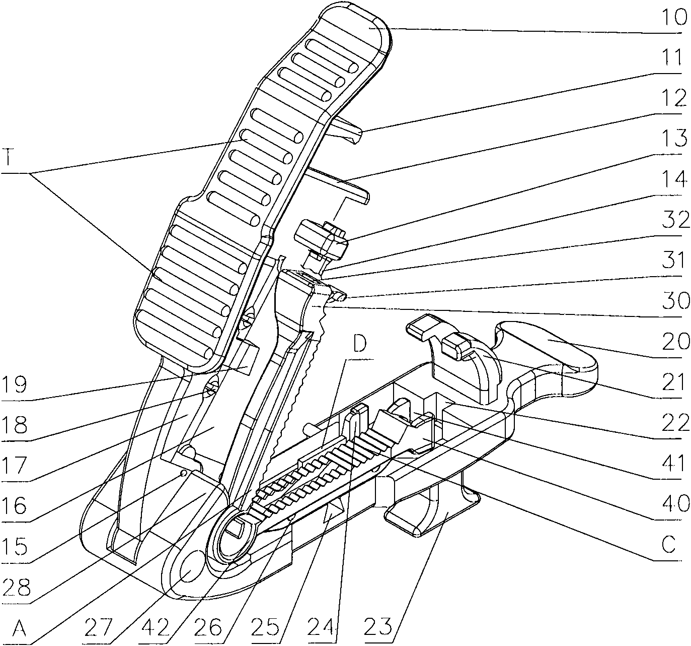
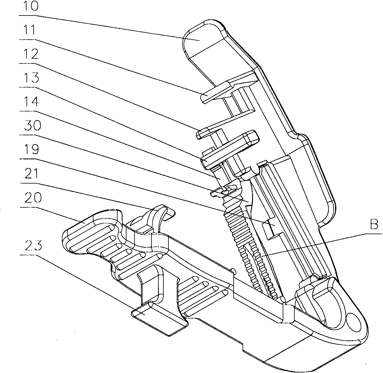
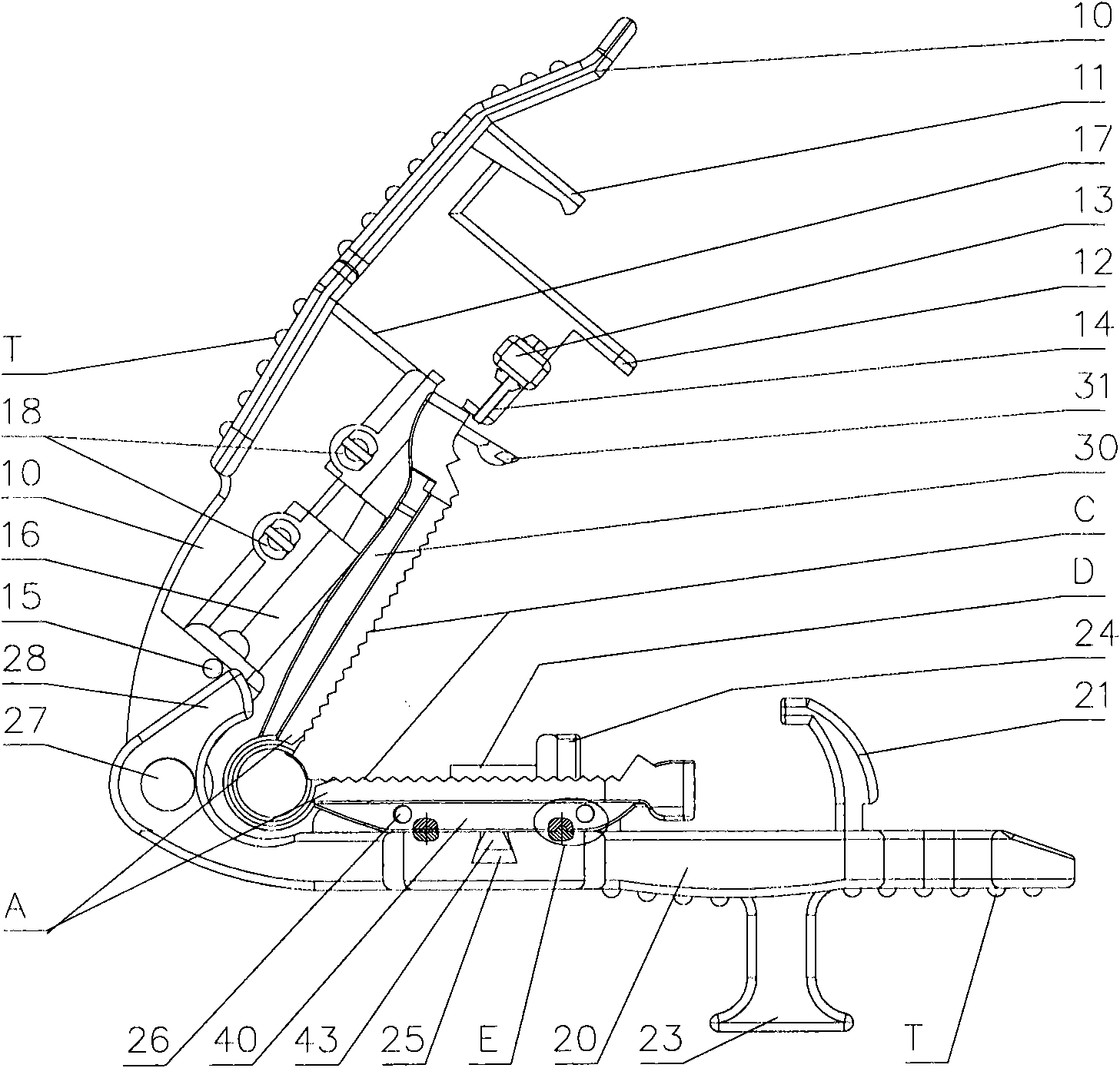
[0037] Embodiment A kind of disposable two-way umbilical cord cutter, comprises the upper housing 10 and the lower housing 20 that rely on the pin shaft 27 to be hinged mutually and the blade fixing frame 17 that is connected with the upper housing 10 as a whole, outside the blade fixing frame 17 The end is provided with the guide rod 12 that is connected with the blade holder 17 as a whole; The hinged end of the lower housing 20 is provided with an inclined first guide arm 28, and the hinged end of the upper housing 10 is slidably fitted into the middle groove of the first guide arm 28; The square groove 22 matched with the end of the rod 12 is provided with a second guide arm 21 on the lower housing 20 outside the square groove 22, and the guide rod 12 is slidably fitted into the middle groove of the second guide arm 21. The outer lower ends of the t...


PUM


Abstract

The invention provides an improvement on a conventional one-time bidirectional umbilical cord cutter. The one-time bidirectional umbilical cord cutter comprises that: an upper shell is provided with a side semi-convex sphere for preventing upper and lower shells from being closed upon a slight external force; one end of a stop body is provided with a stop lever for preventing the umbilical cord from sliding out of an open end of an umbilical clamp; the inner side of a convex pin of the lower shell is provided with an upright semi-convex sphere which is occluded with a spherical groove on the bottom surface of a lower clamping arm and used for preventing the umbilical clamp from transversely slipping; the bottom of the lower shell is provided with a handle for firmly gripping the umbilical cord cutter; the head of an upper clamping arm is provided with a longitudinal flat hole into which hold-down sheets at the two ends of a cross bar of the upper shell are inserted, so that the upper clamping arm and the hold-down sheets are more firmly positioned and occluded; a clamping hook of the upper clamping arm is firmly occluded with a concave platform in the clamping arm groove of the lower clamping arm, so that the upper clamping arm and the lower clamping arm are more firmly closed; a blade is movably arranged on a blade fixing frame through two conjoined elastic split convex pins and is convenient to separate; and when the blade is disassembled, the umbilical cord cutter is completely made of plastic, so the cutter can be recycled as waste plastic.

Description

technical field [0001] The invention relates to an obstetrical medical device, in particular to a disposable bidirectional umbilical cord cutter. Background technique [0002] The invention patent 200910114909.9 applied by the inventor discloses a disposable umbilical cord cutting and umbilical protection device, which can realize the clamping, positioning, cutting, separation and protection of the umbilical cord; the operation process of delivery is simple, fast, safe and reliable, hygienic and sterile blood spattering The amount is small, and the chance of blood spattering, umbilical infection and harming the newborn is minimized, and good positive effects have been obtained; but it still has the following shortcomings: [0003] 1. The small end of the upper shell is only equipped with a limit block to limit the opening angle of the upper shell, but the upper and lower shells are easily closed by external force during transportation or before use, which is inconvenient to ...

Claims


Application Information

Patent Timeline
Patent Type & Authority Applications(China)
IPC IPC(8): A61B17/125A61B17/42
Inventor 曾维著余立群
Owner 江西易通医疗器械有限公司
Why Eureka
Try Eureka