Multi-tube detonation lateral wave ignition device

An ignition device and transverse wave technology, applied in the direction of rocket engine devices, jet propulsion devices, intermittent injection devices, etc., can solve the problems of insufficient specific impulse, difficulty, and lack of competitiveness, and achieve the effect of shortening the length

Inactive Publication Date: 2010-10-13
SHANGHAI UNIV
View PDF4 Cites 10 Cited by
  • Summary
  • Abstract
  • Description
  • Claims
  • Application Information

AI Technical Summary

Problems solved by technology

But it is still very immature, and it faces many technical challenges. At present, almost all pulse detonation engine designs have huge noise, and the operating frequency is obviously difficult to keep up with.
The working frequency refers to the detonation combustion frequency. It takes about 100 Hz to generate enough specific impulse. If this frequency cannot be reached, the specific impulse is not enough, and it is not competitive with the turbine.
Imagine that in a cavity, the exhaust and intake go back and forth more than a hundred times a second, and there is no piston to push the gas out, and only rely on the expansion process to fill, explode, refill, and explode again, which in itself is very difficult
In addition, because the generation and triggering of the detonation wave requires a high temperature and high pressure triggering environment, many researches and designs are aimed at this, such as the shock wave focusing method, the jet ejection detonation method, the step detonation method, and the extended detonation tube How to effectively break through the bottleneck of the DDT process (Deflagration to Detonation Transition) is a problem that has not yet been well resolved.

Method used


Image

  • Multi-tube detonation lateral wave ignition device
  • Multi-tube detonation lateral wave ignition device
  • Multi-tube detonation lateral wave ignition device

Examples


Embodiment Construction

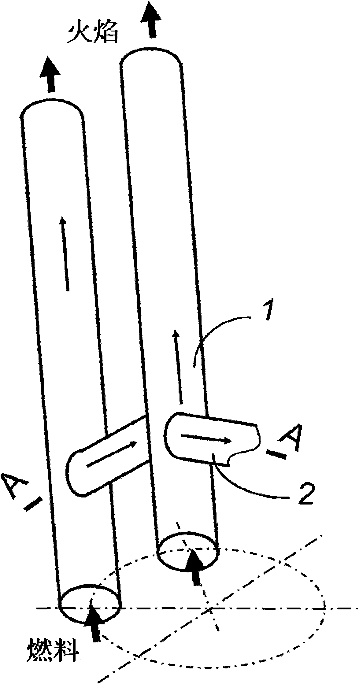
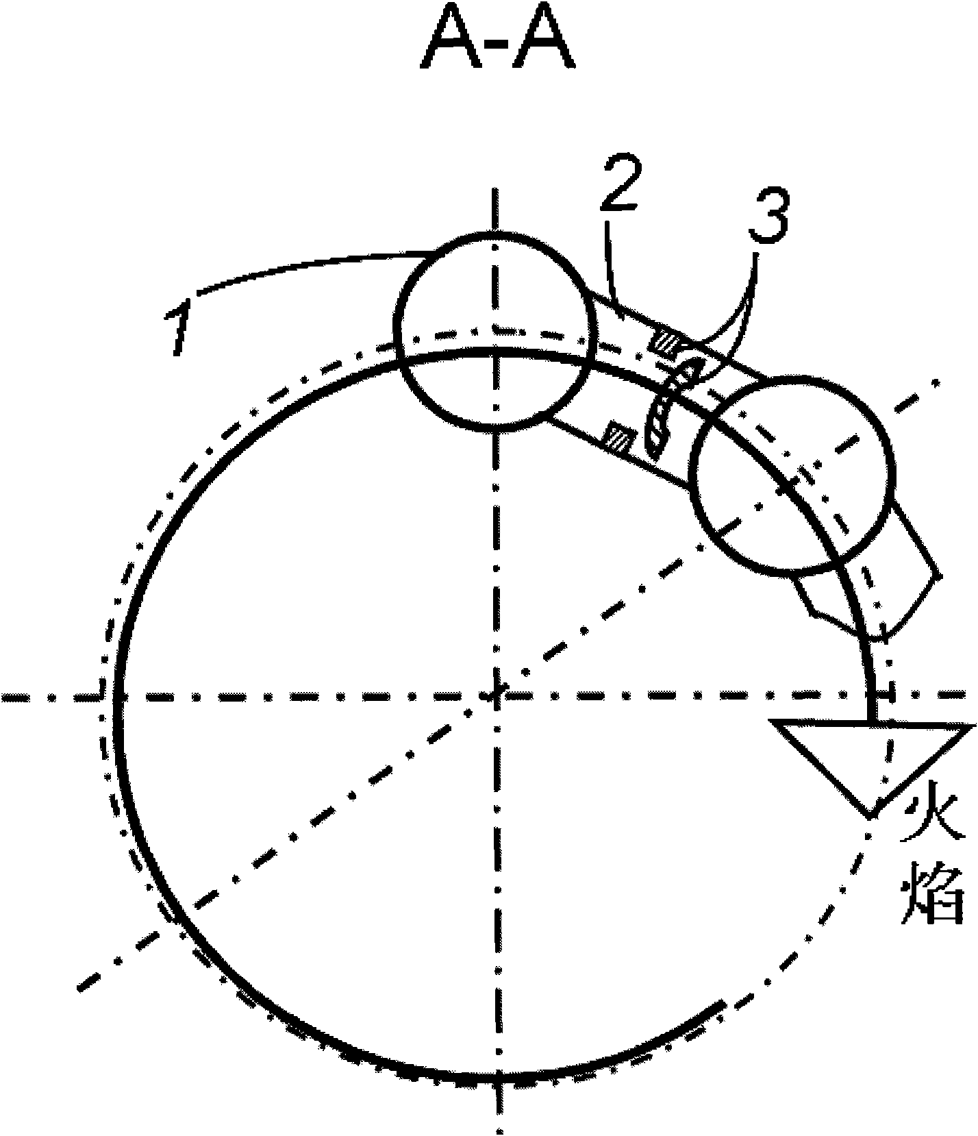
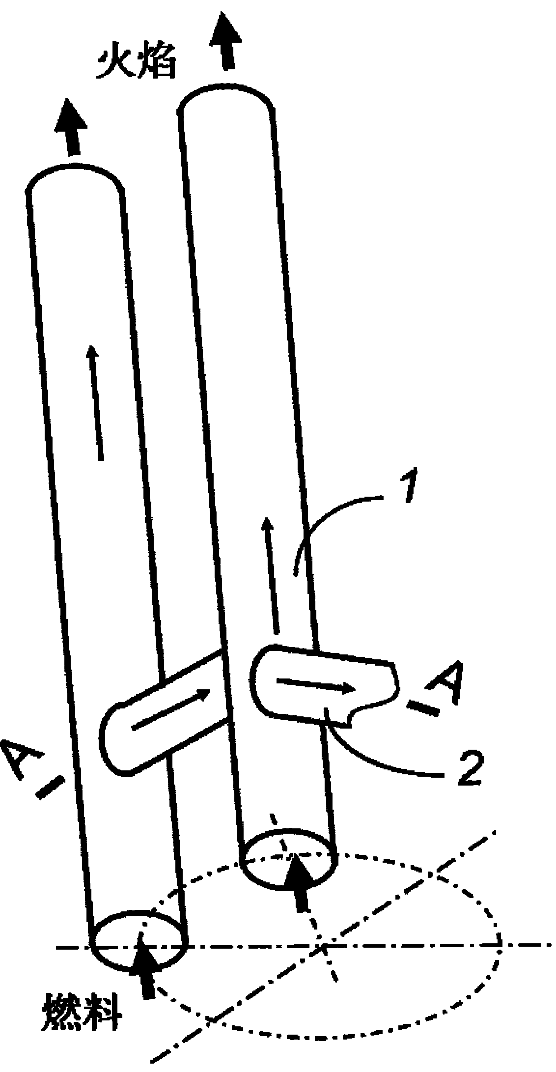
[0030] Preferred embodiment of the present invention is described in detail as follows in conjunction with accompanying drawing: See figure 1 and figure 2 , the multi-tube detonation transverse wave ignition device comprises a plurality of parallel parallel detonation tubes 1, a transverse flame tube 2 and a flame check valve assembly 3, adjacent detonation tubes 1 are formed by a transverse flame tube near the entrance thereof 2 are connected; a flame check valve assembly 3 is arranged in the horizontal flame tube 2; each group of detonation tube 1, horizontal flame tube 2 and flame check valve assembly 3 is arranged in a chain and connected end to end. The premixed fuel that has been charged in the detonation tube 1 is ignited by the ignition device set near the entrance of the detonation tube 1 to generate an initial flame, and the flame propagates in two ways, one is to propagate toward the outlet nozzle of the detonation tube, To generate thrust, the other path passes t...


PUM


Abstract

The invention relates to a multi-tube detonation lateral wave ignition device comprising a plurality of parallel detonation tubes, lateral flame tubes and flame check valve assemblies, wherein the lateral flame tubes are connected with the adjacent detonation tubes and form lateral flame channels of which the tails and the heads are communicated in a system, and the flame check valve assemblies are arranged in the lateral flame tubes. Not only flames in the upstream detonation tubes move to the exit of a spray tube, the branches of the flames also enter the lateral flame tubes, and lateral combustion waves in the tubes move to the adjacent downstream detonation tubes by the flame check valve assemblies to ignite premixed fuels in the downstream detonation tubes to realize combustion; the process is circulated in cycles among the detonation tubes to realize the deflagration to detonation transition (DDT) process of the ignition self-sustaining of a detonation tube system. The invention has simple structure, can meet the demands of high frequency and high-energy ignition and overcome the difficulties of continuous ignition and deflagration to detonation transition. The invention can be used as the ignition realizing mode of a multi-tube pulse detonation engine.

Description

technical field [0001] The invention relates to a multi-tube detonation transverse wave ignition device. It can be used as an ignition device for a multi-tube pulse detonation engine, and can be used in the fields of power or aerospace. Background technique [0002] The present invention arose out of the creation of a similar need for multi-tube pulse detonation engine ignition. [0003] It is generally believed that the development of engines has roughly experienced two major historical stages. The first stage was before 1950, mainly the use of piston engines. In the second stage, after World War II, the turbo engine developed rapidly and has always occupied the dominant position. It has many variants, such as turbofan engine, turboprop engine, turboshaft engine, etc., but its core technology is compressor- Combination of turbines, i.e. gas turbines. [0004] It was asked very early on whether there will be a follow-up model after the turbo engine has passed its peak per...

Claims


Application Information

Patent Timeline
Patent Type & Authority Applications(China)
IPC IPC(8): F02K7/02F02K9/95
Inventor 王志亮徐海丽
Owner SHANGHAI UNIV
Why Eureka
Try Eureka