Tunnel wind-driven generating device
A power generation device, tunnel wind technology, applied in the direction of wind power generation, wind engine, wind motor combination, etc.
- Summary
- Abstract
- Description
- Claims
- Application Information
AI Technical Summary
Problems solved by technology
Method used
Image

Examples
Embodiment 1
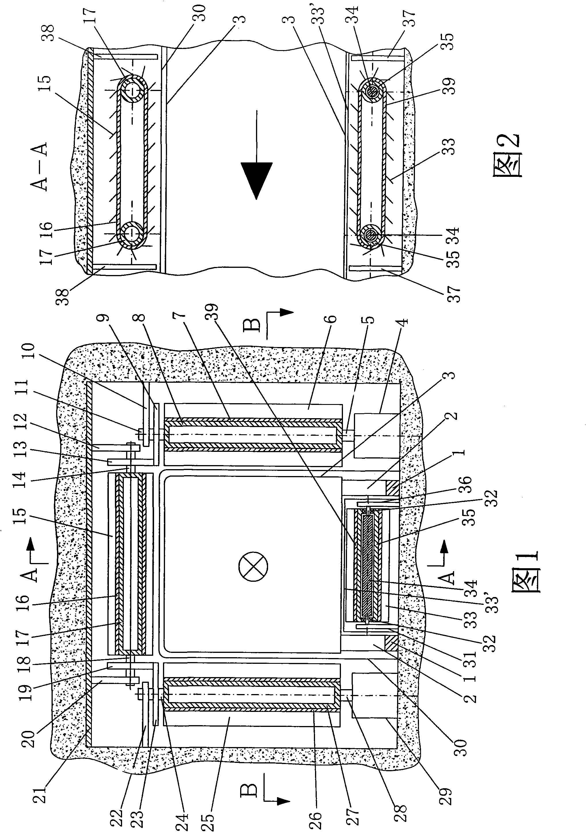
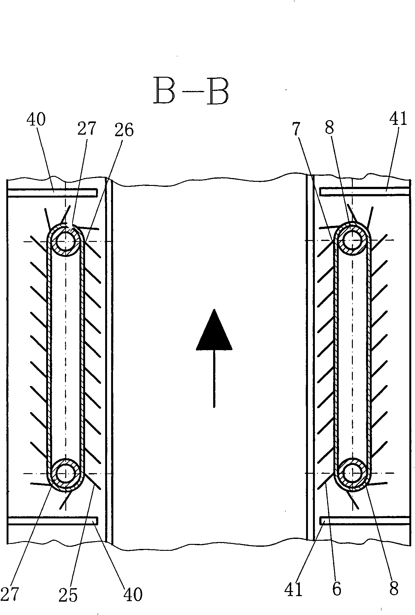
[0038] Embodiment 1: as Figure 1 to Figure 3 The large arrow and the crossed circle indicate the driving direction (the large arrows and the crossed circles in all the drawings in this manual indicate the driving direction); the board 21 is fixed on the top surface of the tunnel, and the hanging board 12 and the hanging board 20 are along the horizontal direction. The bottom surface of the plate 21 is vertically connected at an appropriate distance, the transmission wheel 13 is installed on the right shaft 14 connected with the rotating drum 17, the transmission wheel 19 is installed on the left shaft 18 connected with the rotating drum 17, and the right shaft 14 extends to the transmission wheel 13 Outer end is installed in hanging plate 12 with bearing (not pictured among the figure), and left axle 18 stretches to the outer end of drive wheel 19 and is installed in hanging plate 20 with bearing (not pictured among the figure), and makes rotating cylinder 17 be in Directly ab...
Embodiment 2
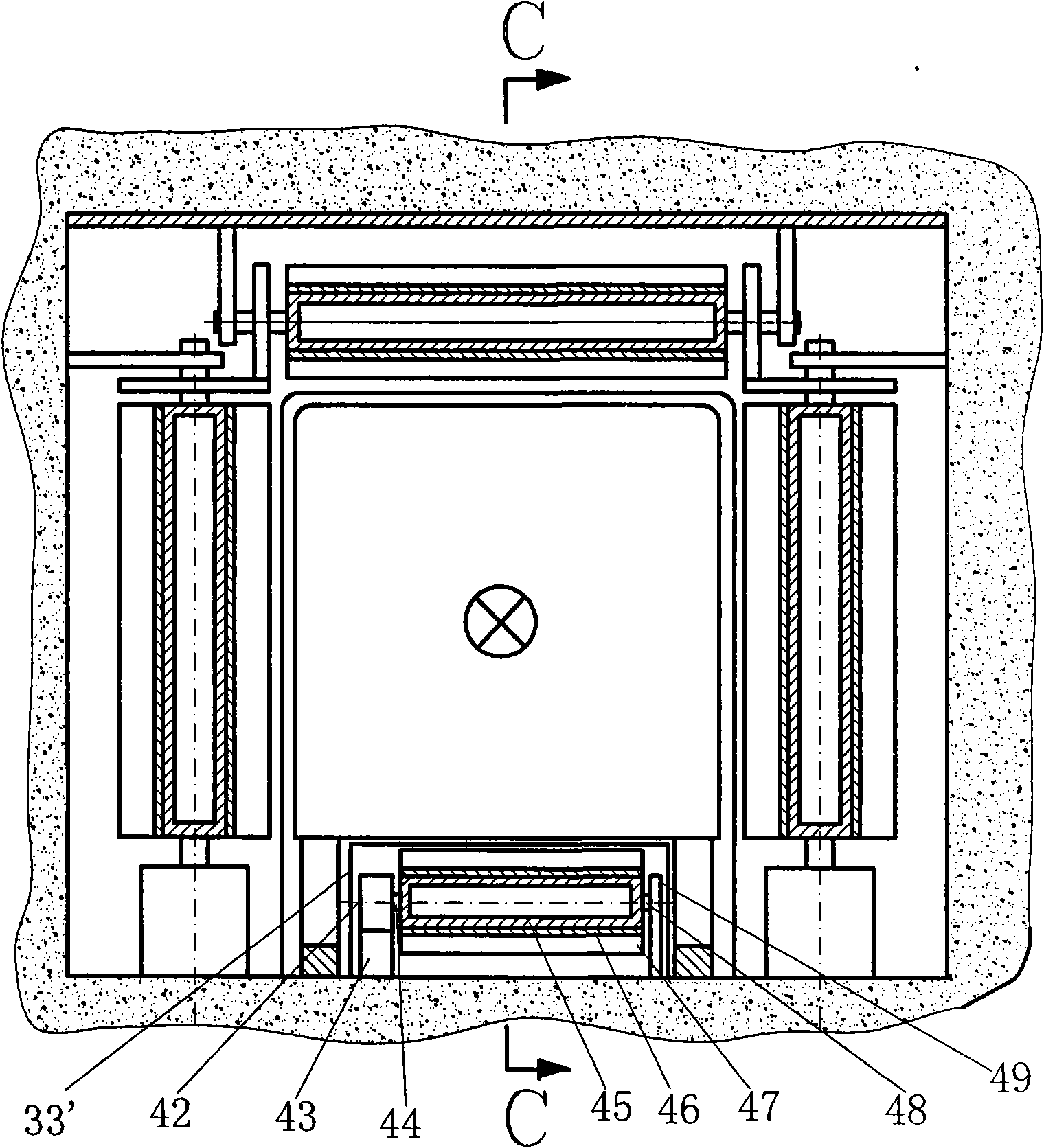
[0044] Embodiment 2: as Figure 6 Figure 7 Shown, the installation method of the upper end of the drum 17', the transmission belt 16', the upper end of the drum 27', and the drum 8' is the same as that of the first type of composition corresponding to the drum 17, the transmission belt 16, the upper end of the drum 27, and the upper end of the drum 8. The installation method of the upper end is the same. The shaft 24' is connected to the center of the lower end surface of the drum 27', and the shaft 24' passes through a bearing (not shown) installed on the support plate 22' and has an interference fit with the bearing. The left end of the support plate 22' is horizontally The direction is fixed vertically on the left wall of the tunnel, and the transmission wheel 23' is installed on the lower end of the shaft 24'; the shaft 11' is connected to the center of the lower end of the drum 8', and the shaft 11' passes through the bearing installed on the support plate 10' (not pic...
Embodiment 3
[0045] Embodiment 3: as Figure 10 to Figure 12 Shown, the installation method of drum 17 ", transmission belt 16 ", upper end of drum 27 ", and upper end of drum 8 "is the same as that of the first type of composition corresponding drum 17, transmission belt 16, upper end of drum 27, and the upper end of drum 8. The installation method of the upper end is the same. The shaft 64 is connected to the center of the lower end surface of the drum 27 ", and the shaft 64 passes through a bearing (not shown in the figure) installed on the support plate 65 and is interference fit with the bearing. The support plate 65 is directly below the support plate 22. The left end of the support plate 65 is vertically fixed on the left wall of the tunnel along the horizontal direction, and the transmission wheel 66 is installed on the lower end of the shaft 64; the shaft 81 is connected to the center of the lower end surface of the drum 8", and the shaft 81 passes through and is installed on the ...
PUM
 Abstract
Description
Claims
Application Information
 - R&D Engineer
- R&D Manager
- IP Professional
- Industry Leading Data Capabilities
- Powerful AI technology
- Patent DNA Extraction
Browse by: Latest US Patents, China's latest patents, Technical Efficacy Thesaurus, Application Domain, Technology Topic.
© 2024 PatSnap. All rights reserved.Legal|Privacy policy|Modern Slavery Act Transparency Statement|Sitemap