
Pneumatic executor for driving valve

A pneumatic actuator and valve-driving technology, which is applied in the direction of valve operation/release devices, valve details, valve devices, etc., can solve the problems of the influence of air supply resistance, fast execution speed, and impossible proportional amplification, etc., and achieve the improvement of action speed Effect

Inactive Publication Date: 2010-10-13
TSINGHUA UNIV
View PDF7 Cites 15 Cited by
  • Summary
  • Abstract
  • Description
  • Claims
  • Application Information

AI Technical Summary

Problems solved by technology

The larger the valve, the larger the cylinder diameter of the pneumatic actuator, and the corresponding increase in air consumption. However, it is impossible to scale up the air supply pipeline matched with the pneumatic actuator, and it is not suitable to scale up in terms of cost. , and the air supply resistance is also affected by the length of the pipeline
Combining these factors that affect the air supply speed, the existing pneumatic actuators have a fast execution speed when driving small valves, such as valves below DN150, but very slow speed when driving large valves.

Method used


Image

  • Pneumatic executor for driving valve
  • Pneumatic executor for driving valve
  • Pneumatic executor for driving valve

Examples


Embodiment Construction

[0017] The present invention will be described in detail below in conjunction with the accompanying drawings and embodiments.

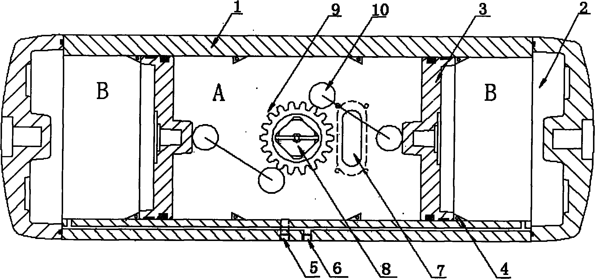
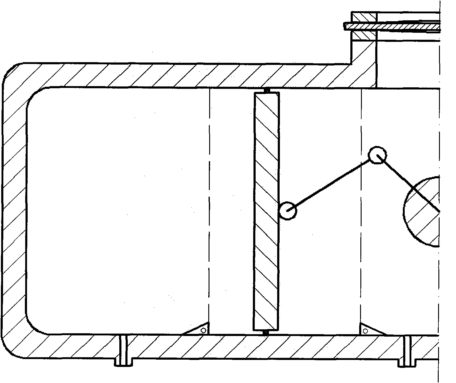
[0018] Such as figure 1 , figure 2 As shown, the present invention includes a cylinder block 1, the two ends of the cylinder block 1 are respectively fixedly connected with a sealing end cover 2, two pistons 3 and corresponding limit mechanisms 4 are arranged in the cylinder block 1, and the two pistons 3 connect the cylinder block 1 Divided into an inner chamber A and two outer chambers B. The cylinder body 1 is provided with two air passages 5, 6, and the inner chamber A and the outer chamber B are respectively provided with air passages 5, 6. There is a vent hole 7 on the wall of the inner cavity A, an actuator shaft 8 is arranged in the center of the cylinder block 1, a gear 9 is arranged on the outer edge of the actuator shaft 8, and two pistons 3 are symmetrically arranged on the inner ends. The rack 10 is meshed with two sides of the gear 9...


PUM


Abstract

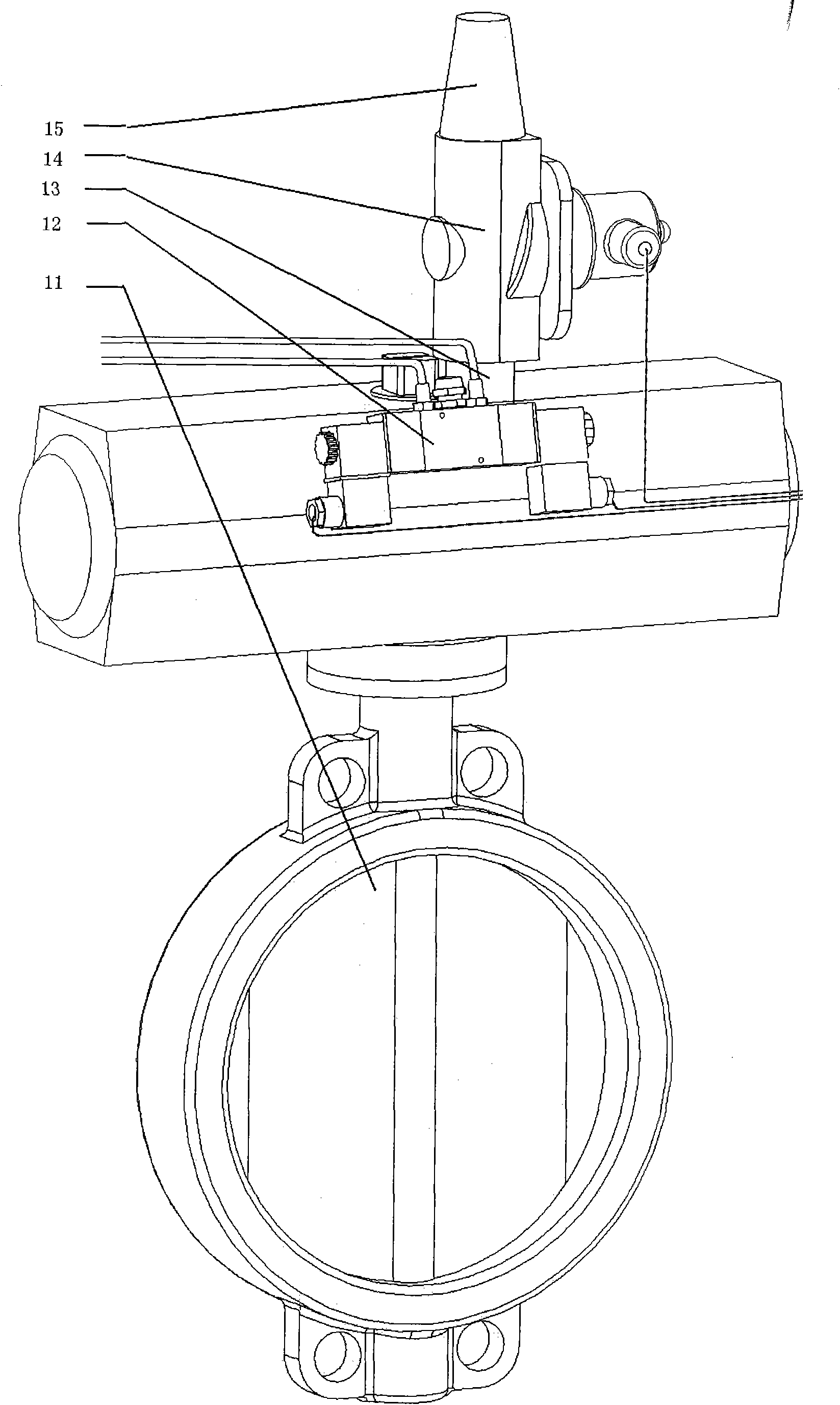
The invention relates to a pneumatic executor for driving a valve, which comprises a cylinder body, a piston arranged in the cylinder body, a limit mechanism of the piston, end covers arranged at two ends of the cylinder body, a transmission mechanism for connecting the piston and an executor shaft driven by the transmission mechanism, wherein the cylinder body is separated into an inner cavity and an outer cavity by the piston, and the inner cavity and the outer cavity are connected with an air source control valve through an air passage. The pneumatic executor is characterized in that the wall of the inner cavity is provided with a vent hole communicated with the atmosphere, a gap is reserved between the hole position of the inner cavity and the limit position of the piston stroke, the area of the hole is not less than 50 percent of the area of the piston, preferably over 1 percent of the area of the piston, and a control valve is arranged outside the vent hole. The opening-closing of the vent hole control valve and linked control of air connection and disconnection of the inner and outer cavities can realize quick communication among the inner and outer cavities, the air source and the atmosphere so as to quickly open and close a butterfly valve and a ball valve according to a set motion order. The pneumatic executor can be widely applied to a driving process of various valves with large calibers of over 200 millimeters.

Description

technical field [0001] The invention relates to a pneumatic actuator for a valve, in particular to a pneumatic actuator capable of driving a valve with a diameter of more than 200 mm. Background technique [0002] The existing pneumatic actuators in the market for driving valves such as butterfly valves and ball valves generally have a cylinder-piston structure, which uses gas pressure to drive the piston to make a linear motion in the cylinder, and then uses gears, racks, shift forks, linkages and other structures to move the piston. Motion is the rotation of the actuator shaft. The actuator shaft then outputs power to the valve stem through the coupling, thereby driving the valve to rotate. In order to make the actuator shaft only bear the torque but not the bending moment, there are generally two relatively moving pistons in the pneumatic actuator, which drive the actuator shaft symmetrically. These two pistons divide the cylinder into two outer cavities and one inner c...

Claims


Application Information

Patent Timeline
Patent Type & Authority Applications(China)
IPC IPC(8): F16K31/122F16J10/02
Inventor 王子羲林嘉赵京辉付军林李建清
Owner TSINGHUA UNIV
Learn More