Sealing device for lamp

A technology for sealing devices and lamps, applied in lighting devices, gas/waterproof devices, components of lighting devices, etc., can solve the problems of difficulty in opening the lamp housing, reducing the service life of the sealing ring, and time-consuming, so as to ensure the sealing and waterproofing effect. , Prolonged service life, good strength and elasticity

Inactive Publication Date: 2010-10-13
OCEANS KING LIGHTING SCI&TECH CO LTD +1
View PDF7 Cites 2 Cited by
  • Summary
  • Abstract
  • Description
  • Claims
  • Application Information

AI Technical Summary

Problems solved by technology

[0003] However, since the volume of the above-mentioned large lamps is usually relatively large, in order to improve the sealing level, it is usually necessary to exert a certain amount of pressure on the sealing ring when assembling the lamps. Although this ensures the sealing performance, it also causes the following problems: 1. To achieve a good seal, it is necessary to increase the friction and exert a certain amount of pressure on the rubber sealing ring. However, when it is necessary to open the lamp housing to replace its internal light source components and other parts, due to the high pressure during assembly, it leads to It is difficult to open the lamp housing during disassembly, and even requires a lot of people to complete it, which is time-consuming and laborious, which increases labor costs and causes great inconvenience to maintenance
2. When opening the lamp housing, it is inevitable that the rubber sealing ring will be damaged due to excessive force, which will affect the later sealing effect of the lamp and cause safety hazards. At the same time, the service life of the sealing ring will be greatly reduced, and the replacement cost will be increased.

Method used


Image

  • Sealing device for lamp
  • Sealing device for lamp
  • Sealing device for lamp

Examples


Embodiment Construction

[0025] In order to make the technical problems, technical solutions and beneficial effects to be solved by the present invention clearer, the present invention will be further described in detail below in conjunction with the accompanying drawings and embodiments. It should be understood that the specific embodiments described here are only used to explain the present invention, not to limit the present invention.

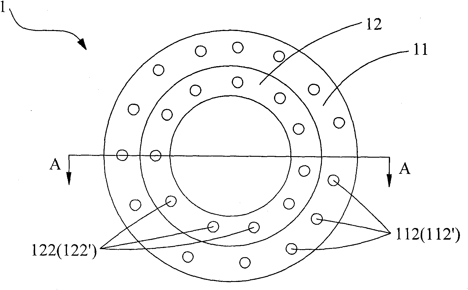
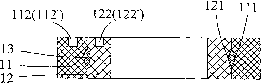
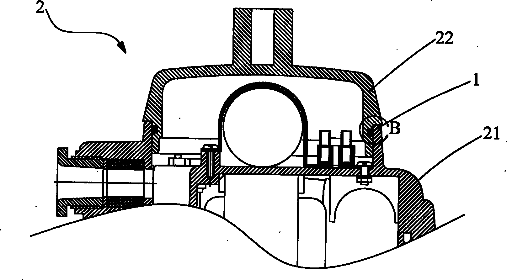
[0026] A sealing device for a lamp provided by the present invention includes a first sealing ring and a second sealing ring used in conjunction, and the contact surfaces of the first sealing ring and the second sealing ring are provided with filling lubricating rings. agent groove. The sealing device used for lamps in the present invention adopts two sealing rings. Compared with one sealing ring in the prior art, the strength and elasticity of the two sealing rings are better when used together. For a single sealing ring in the radial or axial direction The thick...


PUM


Abstract

The invention relates to a sealing device used for a lamp. The sealing device comprises a first sealing ring and a second sealing ring which are cooperatively used, wherein grooves are formed on both contact surfaces of the first sealing ring and the second sealing ring which are matched, and the grooves are formed full of lubricant. The sealing device for the lamp adopts two sealing rings, and compared with the prior art which adopts one sealing ring, the sealing device has the advantages that: the strength and the elasticity are higher due to the cooperatively used two sealing rings; the requirements on radial thickness or axial thickness of a single sealing ring of the two sealing rings are lower than those of the original one sealing ring; and the processing and the processing are easier. Simultaneously, the lubricant is filled between the two sealing rings; and therefore, on the one hand, the effect of sealing and waterproofing of the lamp is ensured, and on the other hand, the friction between the lamp and the two sealing rings are greatly reduced through the lubrication action of the lubricant when the lamp are disassembled, the lamp can be disassembled by only applying little force, time and labor are saved, damage on the sealing rings due to overstress in the disassembling is avoided, the service life of the sealing rings is prolonged, and the cost is saved.

Description

technical field [0001] The invention relates to the technical field of sealing fittings, in particular to a sealing device for lamps. Background technique [0002] In the field of lighting technology, some large lamps need to be installed in special occasions, such as environments with high requirements for explosion-proof and waterproof. In these environments, the interior of the lamp is required to be completely isolated from the external environment, that is, the lamp is required to have a good sealing effect. In the prior art, seals are usually used to achieve sealing. For example, some large fixed lamps generally include a back cover, a housing, a transparent member, and a light source assembly located between the back cover and the lamp housing. In order to achieve a good seal, an annular groove is generally provided on the back cover, and a rubber sealing ring is arranged in it to seal the gap between the back cover and the housing. [0003] However, since the volu...

Claims


Application Information

Patent Timeline
Patent Type & Authority Applications(China)
IPC IPC(8): F21V31/00
Inventor 周明杰彭云龙
Owner OCEANS KING LIGHTING SCI&TECH CO LTD
Why Eureka
Try Eureka