Microchannel heat exchanger

A micro-channel heat exchanger and flow-through technology, which is applied in the direction of heat exchange equipment, heat exchanger type, heat exchanger shell, etc., can solve the problem of uneven flow distribution of refrigerant, and achieve the solution of uneven flow distribution and structural design reasonable effect

Inactive Publication Date: 2010-10-13
SANHUA HLDG GRP +1
View PDF0 Cites 24 Cited by
  • Summary
  • Abstract
  • Description
  • Claims
  • Application Information

AI Technical Summary

Problems solved by technology

[0007] In view of the above defects, the technical problem solved by the present invention is to provide a microchannel heat exchanger to balance the flow resistance of each process and solve the problem of uneven distribution of refrigerant flow

Method used


Image

  • Microchannel heat exchanger
  • Microchannel heat exchanger
  • Microchannel heat exchanger

Examples


Embodiment 1

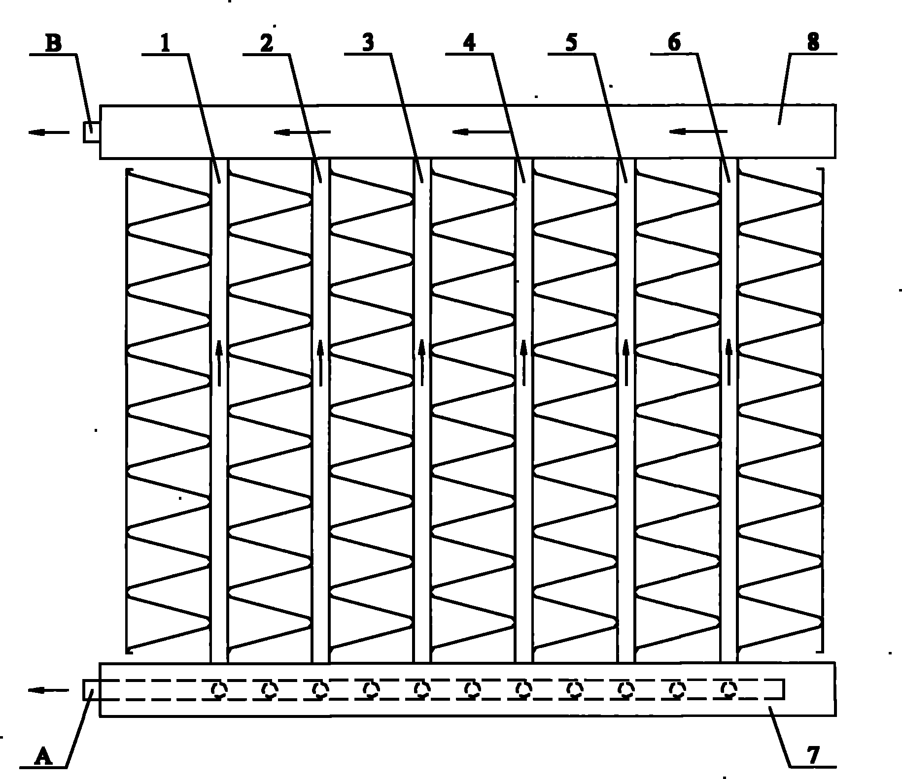
[0028] The composition of the micro-channel heat exchanger in this embodiment and the connection relationship between the components are the same as those in the prior art, and will not be described in detail herein. The overall structure can be found in figure 1 .

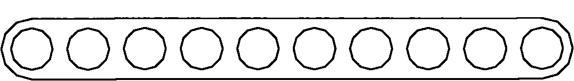
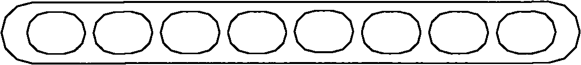
[0029] In this example, the flow resistance of each flat tube is adjusted by changing the flow area of ​​each flat tube. For details, please refer to figure 2 , image 3 and Figure 4 , respectively show the schematic cross-sections of three flat tubes with different flow areas. As shown in the figure, relatively speaking, figure 2 The flat tube shown in is a small-diameter flow hole, image 3 The flat tubes shown in are medium-bore flow holes, Figure 4 The flat tube shown in is a large bore orifice.

[0030] Without loss of generality, the following figure 1 The six flat tubes shown in are taken as an example to illustrate the arrangement of flat tubes with different flow apertures.

[0031] The flow...

Embodiment 2

[0035] In this example, the flow resistance of each flat tube is also adjusted by changing the flow area of ​​each flat tube. For details, please refer to Figure 5 , Figure 6 and Figure 7 , respectively show the schematic cross-sections of three kinds of flat tubes with different widths. As shown in the figure, relatively speaking, Figure 5 The flat tube shown in has a smaller width, Figure 6 The flat tubes shown in have wider widths, Figure 7 The width of the flat tube shown in is the largest.

[0036]The arrangement principle of flat tubes with different widths in this embodiment is the same as that in Embodiment 1. The flow resistance of the first flat tube 1 and the second flat tube 2 is small, and the Figure 5 Smaller width flat tubes shown in . The process resistance of the third flat tube 3 and the fourth flat tube 4 is relatively large, and the Figure 6 Wider width flat tubes shown in . The flow resistance of the fifth flat tube 5 and the sixth flat t...

Embodiment 3

[0040] In this example, the flow resistance of each flat tube is also adjusted by changing the flow area of ​​each flat tube. For details, please refer to Figure 8 , Figure 9 and Figure 10 , respectively show the schematic cross-sections of three flat tubes with different thicknesses. As shown in the figure, relatively speaking, Figure 8 The thickness of the flat tube shown in is smaller, Figure 9 The thickness of the flat tube shown in is wider, Figure 10 The thickness of the flat tube shown in is the largest.

[0041] The arrangement principle of flat tubes with different thicknesses in this embodiment is the same as that in Embodiments 1 and 2. The flow resistance of the first flat tube 1 and the second flat tube 2 is small, and the Figure 8 Flat tubes of smaller thickness shown in . The process resistance of the third flat tube 3 and the fourth flat tube 4 is relatively large, and the Figure 9 Wider flat tubes of thickness shown in . The flow resistance o...


PUM


Abstract

The invention discloses a microchannel heat exchanger, which comprises two collector tubes, a plurality of flat tubes and a plurality of fins, wherein the ends of the two collector tubes on the same side are respectively provided with a refrigerant inlet and a refrigerant outlet; the flat tubes are orderly arranged between the two collector tubes in the longitudinal direction of the collector tubes, and each flat tube is provided with a plurality of flow holes which are respectively communicated with the two collector tubes; each fin is arranged between adjacent flat tubes; and the flow resistance of the flat tubes gradually decreases from the inlet and outlet of the collector tubes, thereby balancing the flow resistance in each flow path. The invention effectively solves the problem of nonuniform refrigerant flow distribution, and preventing unfavorable partial heat emission from affecting the heat exchange efficiency of the complete machine. Preferably, the variation in the flow resistance of the flat tube is the variation of flow area of the flat tube. Preferably, the density of each flat tube is changed, so that different partial regions have different refrigerant flows. The invention has the advantage of reasonable and reliable structural design.

Description

technical field [0001] The invention relates to the technical field of heat and mass exchange, in particular to a microchannel heat exchanger. Background technique [0002] The heat exchanger has experienced the development process from the tube-fin type to the micro-channel parallel flow heat exchanger. Compared with the traditional tube-fin heat exchanger, the microchannel heat exchanger has the characteristics of high heat transfer coefficient, high surface area-volume ratio, low heat transfer temperature difference, low flow resistance, etc., and its energy efficiency and reliability are high. It is mainly used in Residential, light commercial air conditioning and refrigeration and refrigeration markets. [0003] The existing microchannel heat exchanger is mainly composed of a liquid collecting pipe, a microchannel flat tube, fins and side plates. See figure 1 , which is a schematic diagram of the overall structure of an existing microchannel heat exchanger. As shown...

Claims


Application Information

Patent Timeline
Patent Type & Authority Applications(China)
IPC IPC(8): F28D1/053F28F1/02
CPCF28F9/0273
Inventor 刘华钊黄宁杰
Owner SANHUA HLDG GRP
Why Eureka
Try Eureka