Novel secondary air system for opposed firing boiler and working method thereof

A technology of hedging combustion and secondary air, applied in combustion methods, combustion equipment, transportation of non-combustible liquids/gases, etc., can solve the problem of uneven flow distribution in the secondary air box, and solve the problem of uneven flow distribution and facilitate uniform distribution. Effect

Active Publication Date: 2019-08-09
HUADIAN ELECTRIC POWER SCI INST CO LTD
View PDF18 Cites 1 Cited by
  • Summary
  • Abstract
  • Description
  • Claims
  • Application Information

AI Technical Summary

Problems solved by technology

[0005] The purpose of the present invention is to overcome the above-mentioned deficiencies in the prior art, and provide a new type of secondary air system and its working method for opposing combustion boilers, which innovatively adopts the bottom air intake of the secondary air box to realize secondary air flow. There is no dust accumulation at the bottom of the air box, and several secondary air branch pipes are used to enter the air from the bottom of the secondary air box respectively, which is conducive to the uniform distribution of the secondary air and effectively solves the problem of uneven flow distribution of the secondary air box in the counter combustion system

Method used


Image

  • Novel secondary air system for opposed firing boiler and working method thereof
  • Novel secondary air system for opposed firing boiler and working method thereof

Examples


Embodiment Construction

[0022] The present invention will be further described in detail below in conjunction with the accompanying drawings and examples. The following examples are explanations of the present invention and the present invention is not limited to the following examples.

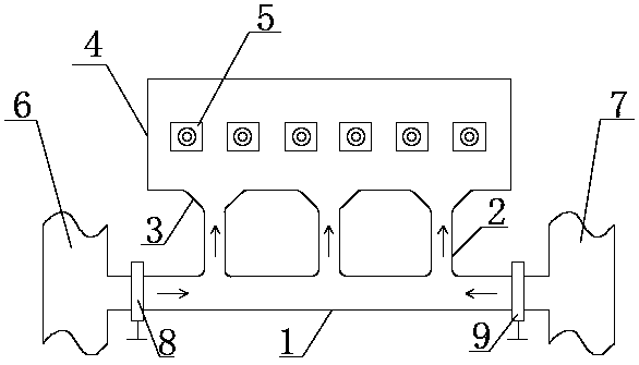
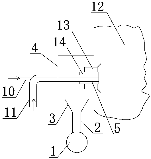
[0023] see Figure 1 to Figure 2 , the new secondary air system used in this embodiment for opposed combustion boilers includes secondary air layer pipe 1, secondary air branch pipe 2, flare 3, secondary air box 4, burner 5, A side secondary air Main duct 6, B-side secondary air main duct 7, A-side regulating damper 8, B-side regulating damper 9, central air duct 10, primary air duct 11, outer secondary air door 13 and inner secondary air door 14.

[0024] The secondary air layer pipe 1 is connected to the secondary air box 4 through the secondary air branch pipe 2, and the flare 3 is located between the secondary air branch pipe 2 and the secondary air box 4; one end of the secondary air layer pipe 1 is connected t...


PUM


Abstract

The invention discloses a novel secondary air system for an opposed firing boiler and a working method thereof. A secondary air layer pipeline is connected with a secondary air box through a secondaryair branch pipe, and a flare is arranged between the secondary air branch pipe and the secondary air box; one end of the secondary air layer pipeline is connected with an A side secondary air main pipeline, and the other end of the secondary air layer pipeline is connected with a B side secondary air main pipeline; a combustor is provided with a central air pipe, a primary air pipe, an outer secondary air door and an inner secondary air door, wherein the outer secondary air door is arranged in the middle of the combustor, the inner secondary air door is arranged at the inner side of the outersecondary air door, the central air pipe is partially sleeved with the primary air pipe, and the primary air pipe is arranged at the inner side of the inner secondary air door; and the secondary airbox communicates with a hearth through the combustor. By supplying air from the bottom of the secondary air box innovatively, no ash is accumulated at the bottom of the secondary air box; and by supplying air from the bottom of the secondary air box respectively through the plurality of secondary air branch pipes, the problem of uneven flow distribution of the secondary air box of an opposed firing combustion system is effectively solved.

Description

technical field [0001] The invention relates to a novel secondary air system and its working method for opposing combustion boilers. Background technique [0002] In the current counter-fired boiler, the secondary air is fed by a public air box, and the secondary air box is divided into a front air box and a rear air box, and the front and rear air boxes are divided into small air boxes according to the number of burner layers, that is, each layer of Share a bellows, the shape of the bellows is cuboid, due to the air intake from both sides of each layer of small bellows, the pressure distribution along the width direction of the bellows is uneven (high pressure in the middle, small pressure on both sides), resulting in the burner in the middle part being in an oxygen-enriched combustion state , the emission concentration of nitrogen oxides is very high, the burners on both sides are in the state of oxygen-deficient combustion, and the high-temperature corrosion is very serio...

Claims


Application Information

Patent Timeline
Patent Type & Authority Applications(China)
IPC IPC(8): F23L9/00
CPCF23L9/00Y02E20/34
Inventor 王帅王凯路昆张庆国
Owner HUADIAN ELECTRIC POWER SCI INST CO LTD
Why Eureka
Try Eureka