
Scanning gauge

A technology of scanning gauges and indicator tables, which is applied in the field of scanning gauges, can solve the problems of unrealistic measurement, low rotation accuracy, unreasonable structure, etc., and achieve the effect of simple structure, smooth rotation, and convenient reading

Inactive Publication Date: 2011-12-21
力邦测控设备(洛阳)有限公司
View PDF0 Cites 0 Cited by
  • Summary
  • Abstract
  • Description
  • Claims
  • Application Information

AI Technical Summary

Problems solved by technology

Some enterprises try to install a rotating mechanism on the measuring table to ensure the efficiency of the measurement, but due to its unreasonable structure and low rotation accuracy, it is only suitable for measurement when the tolerance is relatively large, and it cannot be realized for measurement with a relatively small tolerance

Method used


Image

  • Scanning gauge
  • Scanning gauge
  • Scanning gauge

Examples


Embodiment Construction

[0017] The present invention, a kind of scanning gauge, its specific embodiment is:

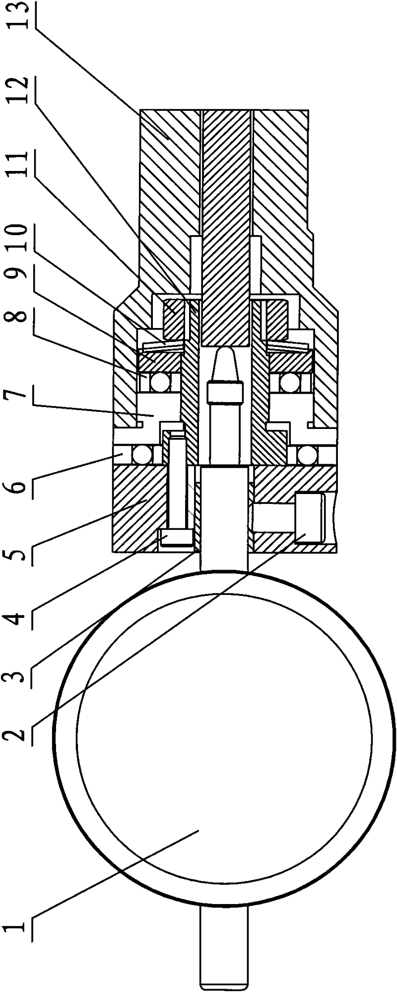
[0018] Such as figure 1 and figure 2 As shown, the measuring head 15, the measuring rod 14, the handle 13, the rotating mechanism 16 and the indicating table 1 are sequentially connected, wherein the other end of the measuring rod 14 passes through the handle 13 and is connected with the contact head of the indicating table 1, and the rotating mechanism 16 will The indicating meter 1 and the handle 13 are connected into an integral structure, and the handle 13 can be rotated arbitrarily, and the indicating meter 1 can be kept still, and the measurement result can be read directly by looking at the meter, so as to achieve the purpose of quick measurement.

[0019] The rotating mechanism 16 includes a table base 5 and a fixed sleeve 12, and one end of the table base 5 is provided with an end face bearing I6, a connecting piece 7, an end face bearing II8, a retaining piece 9, a disc spring 10 ...


PUM


Abstract

The invention discloses a scanning gauge, which comprises a dial gauge, a handle, a measuring rod, and a measuring head. The measuring head passes through the handle; two ends of the measuring rod are connected with the measuring head and the dial gauge respectively; and a rotating mechanism is also arranged between the handle and the dial gauge. The rotating mechanism comprises a gauge stand anda fixing sleeve; and an end face bearing I, a connecting piece, an end face bearing II, a baffle sheet, a disc spring, and a nut are arranged at one end of the gauge stand along the direction of the fixing sleeve in turn. The scanning gauge has the advantages of simple structure and good using effect. Due to the adoption of a double-sided bearing mechanism, the rotation is smooth; the disc springand the nut are connected axially, so that clamping stagnation is not present in the rotating process, and the rotating precision of less than and equal to 0.004 mu m is guaranteed. Meanwhile, the axial gap is eliminated, the measuring error is reduced, and the measuring accuracy is improved. In addition, by only rotating the measuring main body, the aim of measuring and reading at 360 degrees can be fulfilled without changing the viewing angle.

Description

technical field [0001] The invention relates to a mechanical device for detecting the position of a hole, specifically a scanning gauge. Background technique [0002] At present, the main method of measuring the position of the scanning gauge hole: the measuring gauge is fixedly installed on the measuring body. When the worker operates the scanning gauge to measure, the scanning gauge rotates and the measuring gauge also rotates. It is very inconvenient for people to read. When testing in large quantities, the measurement efficiency is very low. Some enterprises try to install a rotating mechanism on the measuring table to ensure the efficiency of the measurement. However, due to its unreasonable structure and low rotation accuracy, it is only suitable for the measurement when the tolerance is relatively large, and it cannot be realized for the measurement with a relatively small tolerance. Contents of the invention [0003] The technical problem to be solved by the prese...

Claims


Application Information

Patent Timeline
Patent Type & Authority Patents(China)
IPC IPC(8): G01B5/08
Inventor 张金英
Owner 力邦测控设备(洛阳)有限公司
Learn More