Voltage adjustment and electricity theft prevention device for motor of oil extractor

A technology for voltage regulation and anti-theft electricity, which is applied in the direction of automatic disconnection of emergency protection devices, circuit devices, AC motor control, etc. good, the effect of improving operating efficiency and power factor

Active Publication Date: 2010-10-13
黑龙江汇诚电气有限公司
View PDF0 Cites 1 Cited by
  • Summary
  • Abstract
  • Description
  • Claims
  • Application Information

AI Technical Summary

Problems solved by technology

[0004] The present invention aims to solve the problem that the existing pumping unit motor cannot realize voltage regulation and

Method used


Image

  • Voltage adjustment and electricity theft prevention device for motor of oil extractor
  • Voltage adjustment and electricity theft prevention device for motor of oil extractor
  • Voltage adjustment and electricity theft prevention device for motor of oil extractor

Examples


specific Embodiment approach 1

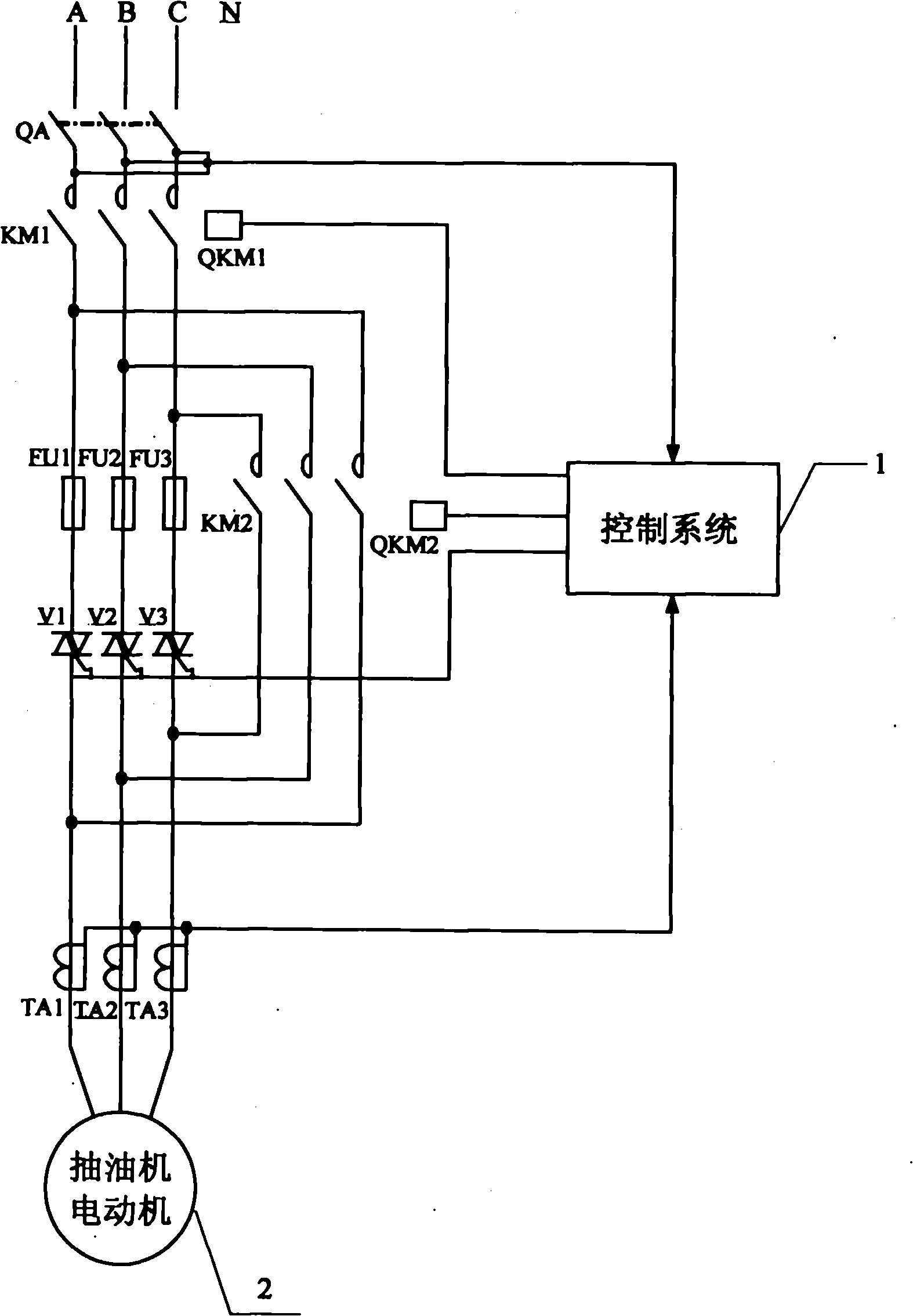
[0008] Specific implementation mode 1. Combination figure 1 Illustrate this specific embodiment, the voltage regulation and anti-theft electric device of pumping unit motor, it comprises pumping unit motor 2, it also comprises first AC contactor KM1, second AC contactor KM2, No. 1 thyristor V1, No. 2 thyristor Thyristor V2, No. 3 thyristor V3, first current transformer TA1, second current transformer TA2, third current transformer TA3 and control system 1, the A-phase static terminal and B-phase static terminal of the first AC contactor KM1 terminal and C-phase static terminal are connected to the three-phase power supply at the same time, and the A-phase dynamic terminal, B-phase dynamic terminal and C-phase dynamic terminal of the first AC contactor KM1 are respectively connected to the power input terminal of the first thyristor V1 and the second thyristor The power input terminal of V2 is connected to the power input terminal of the No. 3 thyristor V3, and the A-phase movi...

specific Embodiment approach 2

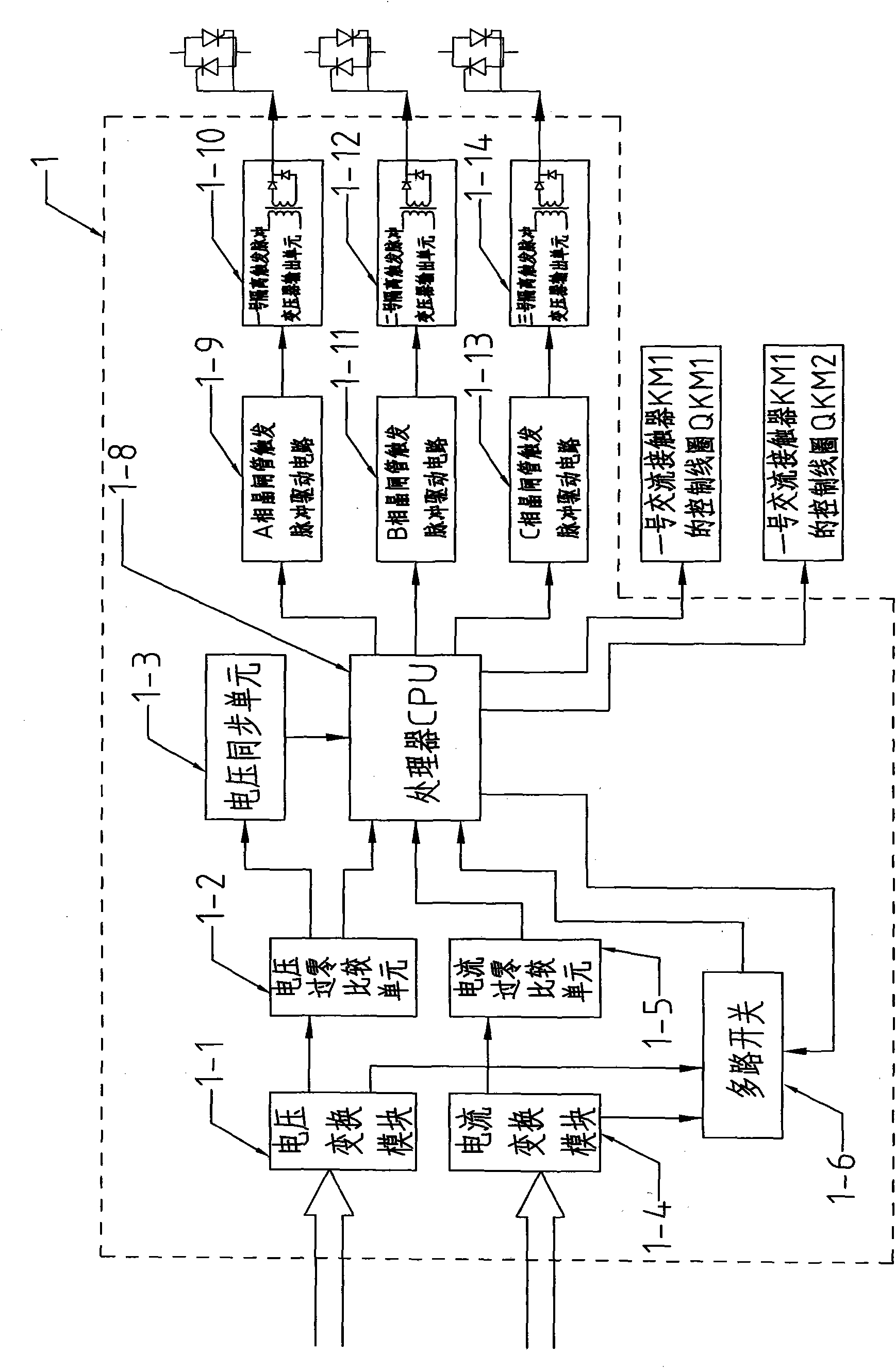
[0015] Specific embodiment two, combine figure 2 Describe this specific embodiment, the difference between this specific embodiment and the voltage regulation and anti-theft electric device of the pumping unit motor described in the first specific embodiment is that the control system 1 includes a voltage conversion module 1-1, a voltage zero-crossing comparison unit 1 -2. Voltage synchronization unit 1-3, current conversion module 1-4, current zero-crossing comparison unit 1-5, multi-way switch 1-6, processor CPU 1-8, A-phase thyristor trigger pulse drive circuit 1-9, No. 1 isolated trigger pulse transformer output unit 1-10, B-phase thyristor trigger pulse drive circuit 1-11, No. 2 isolated trigger pulse transformer output unit 1-12, C-phase thyristor trigger pulse drive circuit 1-13 and No. 2 isolated trigger The pulse transformer output unit 1-14, the No. 1 output terminal of the voltage conversion module 1-1 is connected to the input terminal of the voltage zero-crossing...

specific Embodiment approach 3

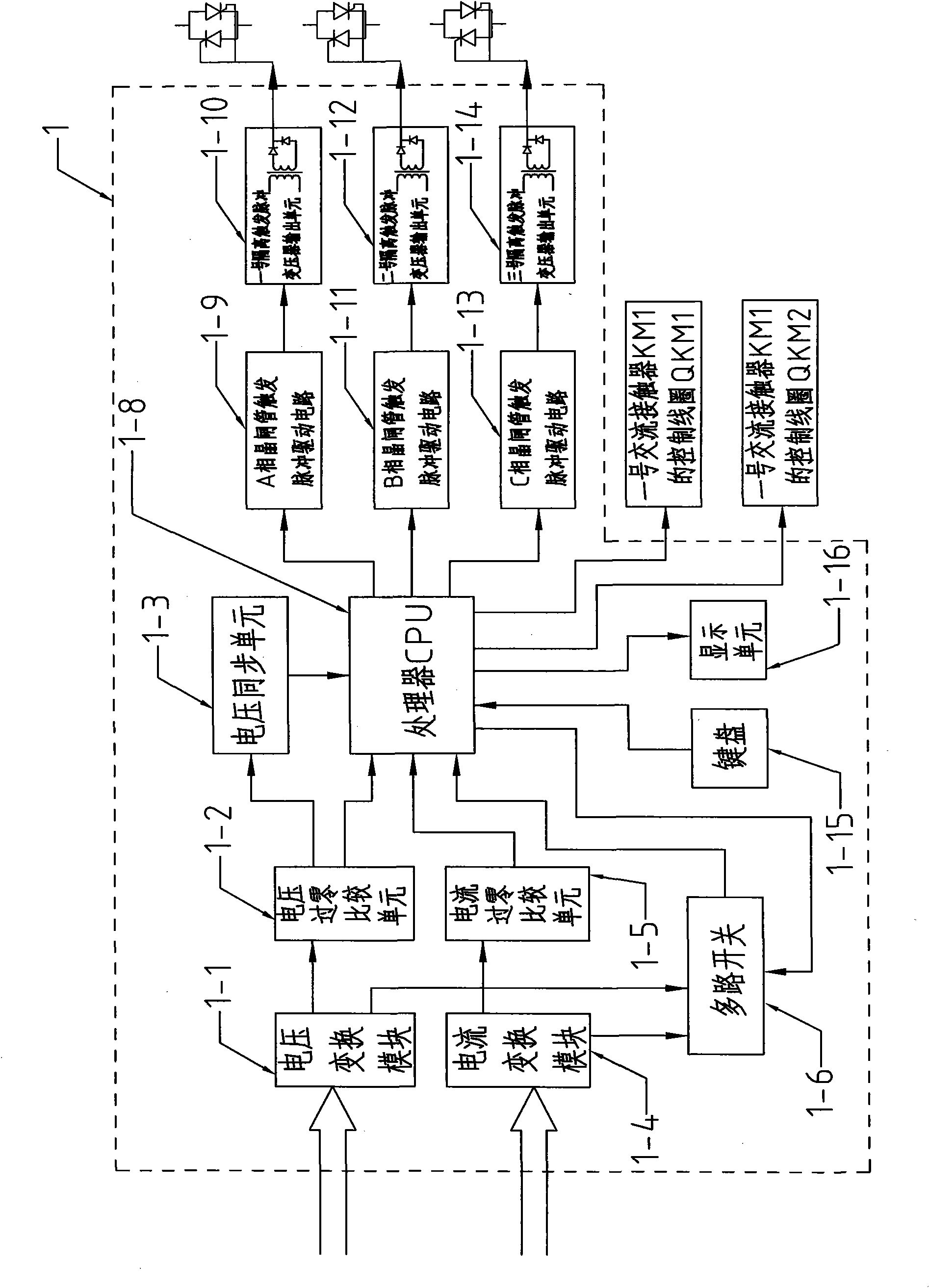
[0020] Embodiment 3. The difference between this embodiment and the voltage regulation and anti-theft electric device of the pumping unit motor described in Embodiment 2 is that it also includes a keyboard 1-15, and the keyboard signal output of the keyboard 1-15 End is connected with the keyboard signal input end of processor CPU1-8.


PUM


Abstract

The invention discloses a voltage adjustment and electricity theft prevention device for a motor of an oil extractor, which relates to a voltage adjustment and electricity theft prevention device and solves the problem that the traditional motor of an oil extractor can not realize voltage adjustment and has poor electricity theft prevention effect. The moving ends of the A, B and C phases of a first alternate current contactor are respectively connected with the power supply input ends of a thyristor No.1, a thyristor No.2 and a thyristor No.3 and the fixed ends of the A, B and C phases of a second alternate current contactor; the power supply output ends of the thyristor No.1, the thyristor No.2 and the thyristor No.3 are respectively connected with the input end of a three-phase power supply of the motor of the oil extractor and the moving ends of the A, B and C phases of the second alternate current contactor; and a control system detects the voltage value of the three-phase power supply and the output current values of the thyristor No.1, the thyristor No.2 and the thyristor No.3; and the trigger pulse signal output end of the control system is connected with the control signal input ends of the thyristor No.1, the thyristor No.2 and the thyristor No.3 simultaneously. The invention is applicable to traditional motors of the oil extractors.

Description

technical field [0001] The invention relates to a voltage regulating and anti-theft electrical device. Background technique [0002] In the oil field, when various types of pumping units are equipped with motors, in order to ensure the normal operation of the pumping units under various working conditions, the motors will have a certain power margin; as the oil well is pumped from shallow to deep, the output of the oil well As the amount of fluid decreases, the load of the pumping unit decreases accordingly. Therefore, the actual load rate of the pumping unit is generally low, and the load rate of most pumping units is between 20% and 30%. The maximum will not exceed 50%, a large amount of electric energy is wasted, the power factor of the motor is low, and the reactive power loss is also relatively large. [0003] And, because the pumping unit is generally all located in the field, the phenomenon of stealing electricity very easily occurs, as stealing electricity at the ou...

Claims


Application Information

Patent Timeline
IPC IPC(8): H02P7/28H02H5/00H02P27/024
Inventor 王东方
Owner 黑龙江汇诚电气有限公司
Why Eureka
Try Eureka