
Distributed two-stage mixing device and method thereof

A mixing device, a decentralized technology, used in mixing methods, mixers, liquid and solid mixing, etc., can solve problems such as the generation of agglomerates

Inactive Publication Date: 2010-10-20
SHANGHAI YI CHEN INFORMATION TECH DEV
View PDF9 Cites 4 Cited by
  • Summary
  • Abstract
  • Description
  • Claims
  • Application Information

AI Technical Summary

Problems solved by technology

However, this device cannot solve the problem of simultaneously adding liquid and solid powder to a high-viscosity solid-liquid mixture and simultaneously avoiding the generation of lumps between the added liquid and solid powder
[0012] In addition to the above, Chinese patents 200510009386.3, 200510042674.9, 200510129550.4, 200510103613.9, etc. also disclose a variety of mixing devices, but the above-mentioned devices still fail to solve the problem of high viscosity solid-liquid The technical problem of uniform mixing of mixtures and liquids, solid powders, additives, etc. in a certain proportion

Method used


Image

  • Distributed two-stage mixing device and method thereof
  • Distributed two-stage mixing device and method thereof
  • Distributed two-stage mixing device and method thereof

Examples


Embodiment 1

[0090] A dispersive two-stage mixing device includes the following parts:

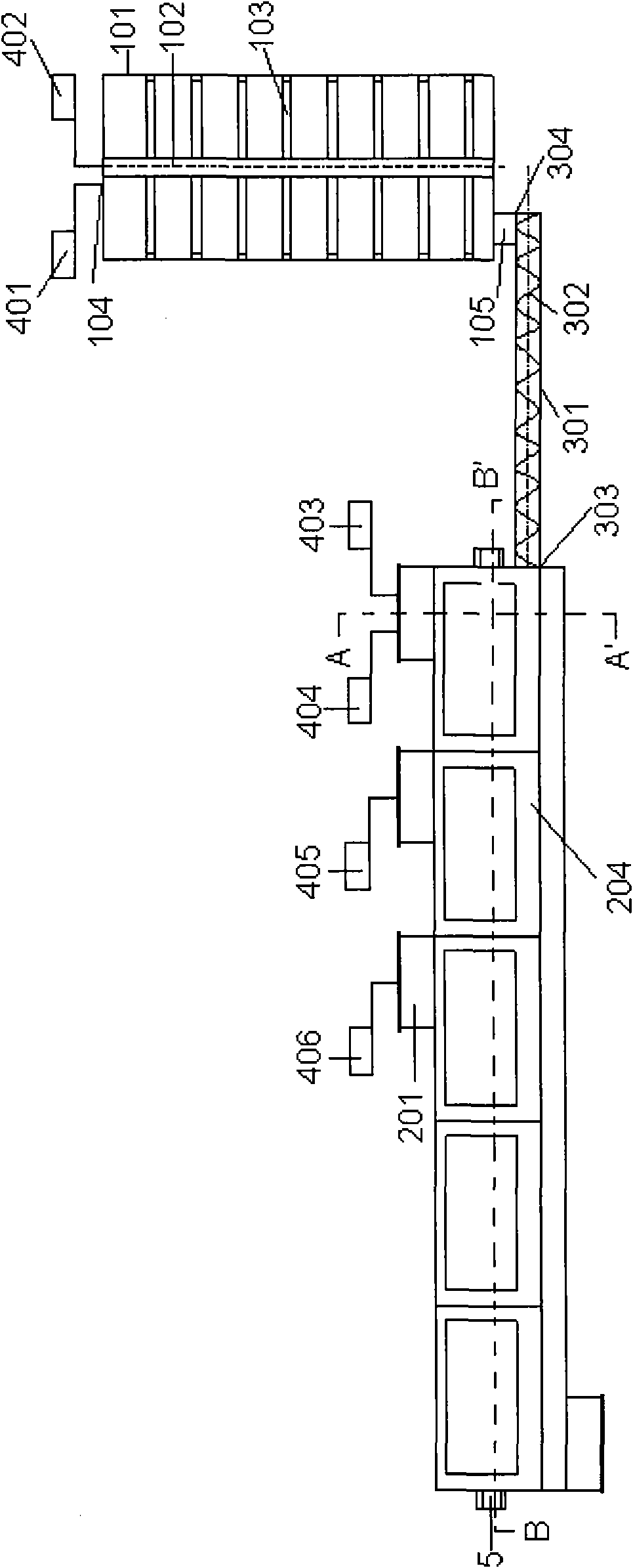
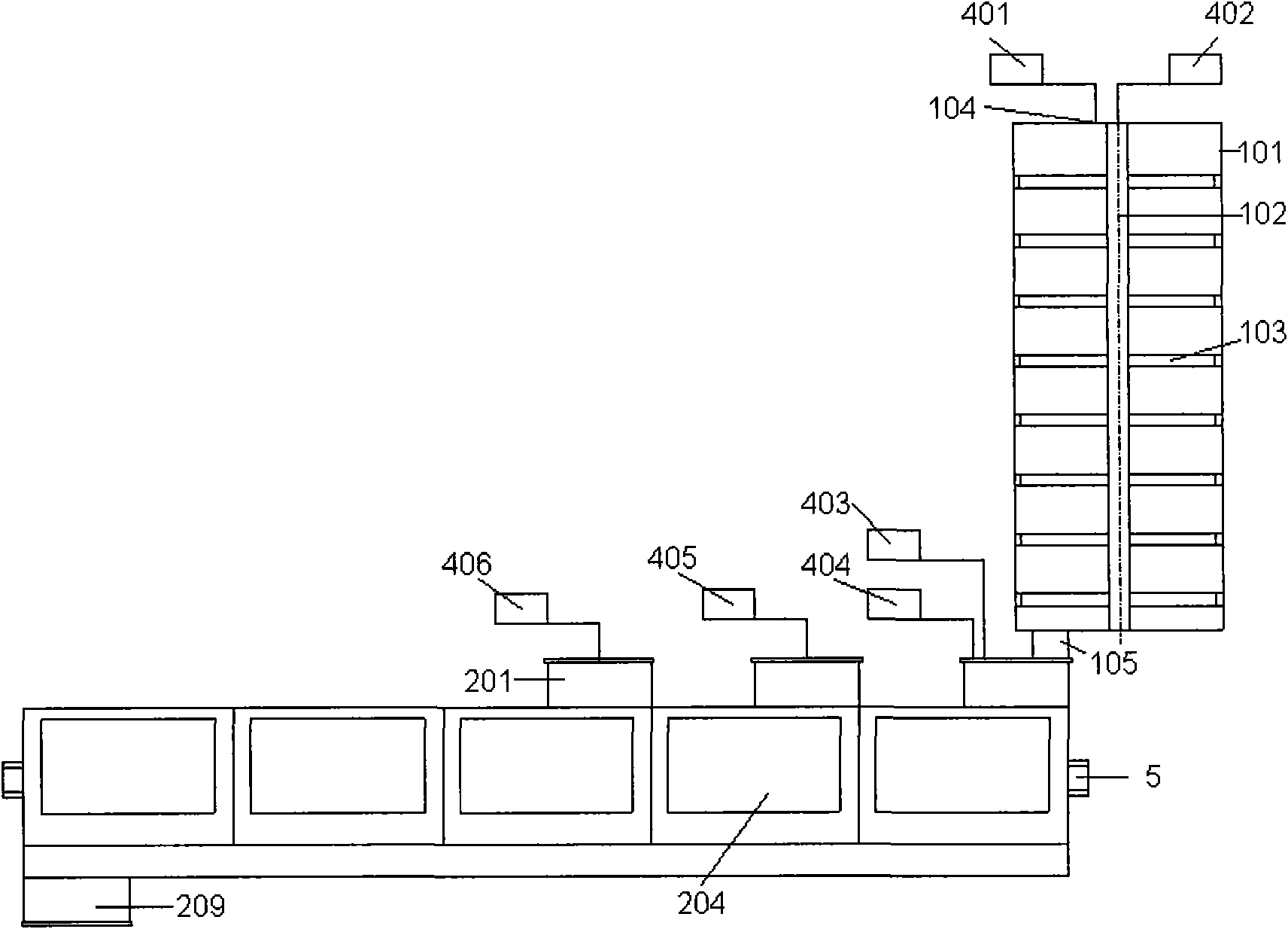
[0091] according to Figure 1a and Figure 1b :

[0092] The two-stage mixing device includes a premixing system 1 , a mixing system 2 , a packing system 4 , a rotating shaft system 5 , a first stirring system 6 , and a second stirring system 7 .

[0093] The pre-mixing system 1 is connected to the mixing system 2 through the delivery system 3, or directly connected to the mixing system 2.

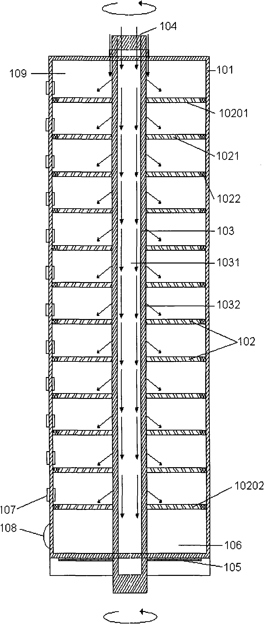
[0094] according to figure 2 and image 3 :

[0095] The premixing system 1 is a cylindrical tower-type mixing reactor formed by a shell 101 and centered on a vertical shaft 103, which contains a group of trays connected to the shaft 103 and rotating therewith. The trays described above are further divided into a first tray group and a second tray group.

[0096] The trays of the first tray group and the second tray group are distributed alternately, and a separate mixing chamber is formed between any two ad...

Embodiment 2

[0166] Adopt following technical parameter to improve embodiment one:

[0167] The ratio of the radii of the housing 101 , the first cavity shell 202 and the second cavity shell 203 is 5:1:1.

[0168] The radius ratio of the first chamber shell 202 and the second chamber shell 203 is 1:1.5.

[0169] The rotational speed ratio of the first rotating shaft 501 , the second rotating shaft 502 and the rotating device 703 is 2:1:1.5.

Embodiment 3

[0171] Adopt following technical parameter to improve embodiment one:

[0172] The ratio of the radii of the housing 101 , the first cavity shell 202 and the second cavity shell 203 is 6:1:1.

[0173] The radius ratio of the first chamber shell 202 and the second chamber shell 203 is 1:2.

[0174] The rotational speed ratio of the first rotating shaft 501 , the second rotating shaft 502 and the rotating device 703 is 4:1:2.


PUM

PropertyMeasurementUnit
Center angleaaaaaaaaaa

Abstract

The invention relates to a distributed two-stage mixing device and a method thereof. The device and the method comprise a premixing system, a mixing system, a filling system, a first agitating system and a second agitating system. The premixing system is a cylindrical tower mixing reactor formed by a shell and using a vertical rotary shaft as a circle center, and a first tower plate group and a second tower plate group, which are connected with the rotary shaft and rotates along with the rotary shaft, is installed in the premixing system. The first agitating system is a group of vane wheels which are connected with a first rotary shaft and rotate along with the first rotary shaft, and each vane wheel comprises 2-4 vanes comprising agitating vanes and scratch plates and having the same angular interval. The second agitating system is a group of vanes which are connected with a second rotary shaft and rotate along with the second rotary shaft, and each vane comprises a rotary shaft, a scratch plate and a rotary device provided with concave and convex gears.

Description

technical field [0001] The invention relates to a two-stage mixing device, in particular to a dispersed two-stage mixing device, which belongs to the field of mechanical mixing equipment. [0002] The invention also relates to a method of mixing using a dispersive two-stage mixing device. Background technique [0003] During the processing of reconstituted rice, it is necessary to uniformly mix the solid powder of the grain with liquids such as water to obtain a solid-liquid mixture with high viscosity, and to the above-mentioned solid-liquid mixture, it is necessary to further uniformly add various solid and / or liquid additives. The above-mentioned various materials need to be evenly distributed in the obtained solid-liquid mixture, so that the content of each substance in the prepared reconstituted rice meets the standard. [0004] Since the solid powder particles of grains are relatively fine, they cannot be dissolved in water, and once mixed with water, they will become...

Claims


Application Information

Patent Timeline
IPC IPC(8): B01F7/18B01F3/12B01F3/14B01F23/57
Inventor 刘英
Owner SHANGHAI YI CHEN INFORMATION TECH DEV
Features
  • Generate Ideas
  • Intellectual Property
  • Life Sciences
  • Materials
  • Tech Scout
  • Unparalleled Data Quality
  • Higher Quality Content
  • 60% Fewer Hallucinations
Learn More