Welding process for broken 34CrNi3Mo electro-hydraulic hammer lever

A welding process and electro-hydraulic hammer technology, applied in welding equipment, manufacturing tools, metal processing equipment, etc., can solve the problems of long time consumption, waste of money, high cost of new hammer rods, etc., and achieve the effect of reducing production costs

Inactive Publication Date: 2010-10-20
韩生
View PDF5 Cites 2 Cited by
  • Summary
  • Abstract
  • Description
  • Claims
  • Application Information

AI Technical Summary

Problems solved by technology

[0002] The domestic forging industry has always been blank in the welding of the broken 34CrNi3Mo electro-hydraulic hammer shaft. Generally, the hammer shaft is scrapped after being broken a

Method used


Image

  • Welding process for broken 34CrNi3Mo electro-hydraulic hammer lever
  • Welding process for broken 34CrNi3Mo electro-hydraulic hammer lever
  • Welding process for broken 34CrNi3Mo electro-hydraulic hammer lever

Examples


Embodiment 1

[0026] This embodiment is suitable for replacing a broken hammer shaft with a base material, that is, a 34CrNi3Mo base material matching the section of the hammer shaft is selected, and the diameter of the base material is slightly larger than the diameter of the hammer shaft. Welded to make a new hammer shaft.

[0027] Its process steps are as follows:

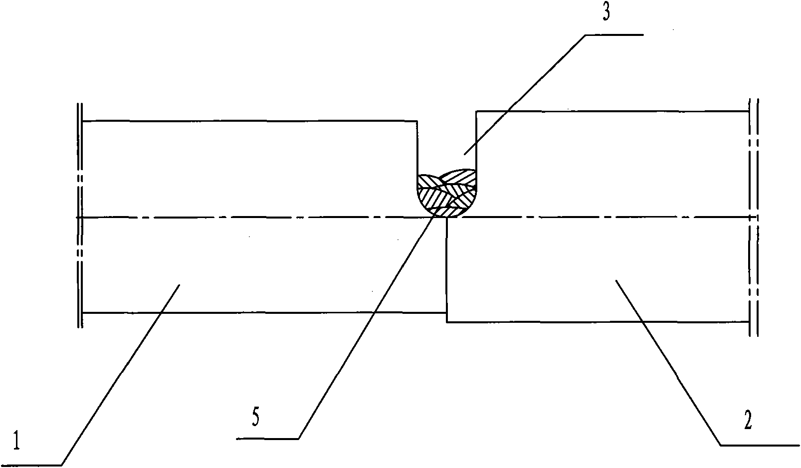
[0028] (1), the broken hammer shaft fracture section 1 is docked with a piece of 34CrNi3Mo base material 2 matching the section;

[0029] (2), at the hammer shaft fracture section 1 described in step (1) and the 34CrNi3Mo base material 2 interface, open the U-shaped groove 3 on one side with the gas cutting mode, (because the base material is carried out very suitable when adopting gas cutting The preheating temperature does not need to be repeated, and the method is simple) The bottom end of the U-shaped groove 3 reaches the horizontal centerline position between the fractured section of the hammer rod and the base material...

Embodiment 2

[0036] This embodiment is suitable for directly welding together the broken two-section hammer shank to restore the hammer shank.

[0037] Its specific process steps are as follows:

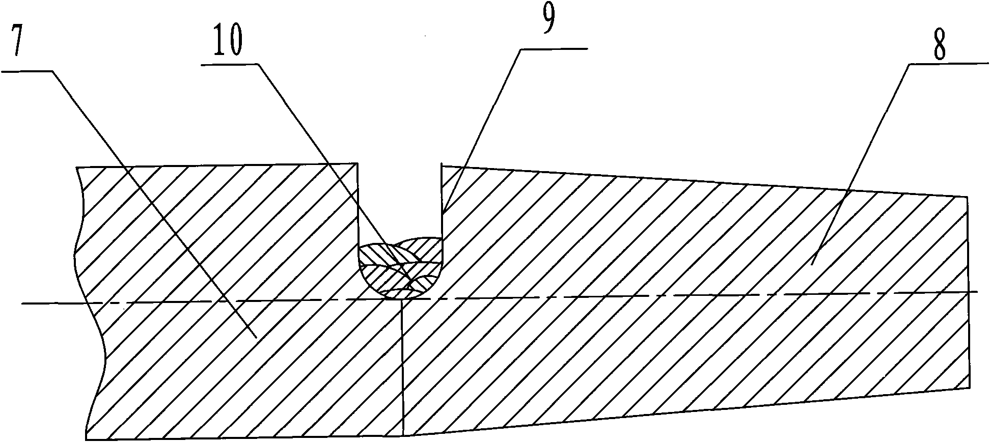
[0038] (1), butt joint placement of the broken two sections of hammer rod fracture sections 7 and 8;

[0039] (2) At the interface of the fractured section of the two hammer shafts, a U-shaped groove 9 is opened on one side by means of gas cutting, and the bottom end of the U-shaped groove 9 reaches the horizontal centerline of the hammer shaft. Add welding material 10, welding material 10 is J107Cr material, and use multi-layer and multi-pass welding for 5-7 times;

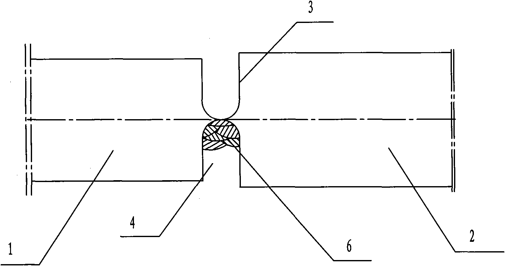
[0040] (3), U-shaped groove 11 is opened on the other side of the two hammer rod fracture sections processed in step (2), and U-shaped groove 11 is opposite to the bottom end of U-shaped groove 9 in step (2). Add welding consumables 12 to the groove 11, and the welding consumables 12 is J107Cr material, which is welded in a multi-...


PUM


Abstract

The invention relates to a welding process for a broken 34CrNi3Mo electro-hydraulic hammer lever, and belongs to the technical field of welding. The method comprises the following steps that: the broken section of the hammer lever is in butt joint with a 34CrNi3Mo base material which is matched with the section; a U-shaped groove is formed on one side of the joint by gas cutting, the bottom of the U-shaped groove reaches the position of the horizontal central line of the hammer lever and the base material, and welding is performed for 5 to 7 times in a multilayer multiway mode by using J107Cr as a welding material; a U-shaped groove is formed on the other side of the joint, welding is performed in the multilayer multiway mode until the welding material is fully filled, the hammer lever is corrected to make the hammer lever and the base material in a line after the welding operation is finished, heat treatment is performed and the temperature is controlled to 800 DEG C to perform oil immersion, tempering and air cooling are performed at the temperature of 520 DEG C to eliminate residual stress and promote tissue uniformization; the repaired hammer lever is subjected to ultrasonic inspection; and the hammer lever after the ultrasonic inspection is passed is processed and molded. The service life of the hammer lever welded by the process is nearly equal to that of a new piece in the application process; and the production cost is greatly reduced without replacing the new piece.

Description

technical field [0001] The invention relates to a welding process, in particular to a welding process for repairing the hammer shaft of a 34CrNi3Mo electro-hydraulic hammer after the shaft is broken. Background technique [0002] The domestic forging industry has always been blank in the welding of the broken 34CrNi3Mo electro-hydraulic hammer shaft. Generally, the hammer shaft is scrapped after being broken and needs to be replaced with a new one. Matching, contacting different manufacturers, in the process of replacing the hammer rod, not only wastes money, but also takes a long time and delays production. Contents of the invention [0003] In order to solve the above existing problems, the present invention provides a welding process for 34CrNi3Mo electro-hydraulic hammer after the hammer shaft is broken, which is firm and durable, avoids waste and reduces production cost. [0004] The purpose of the present invention is achieved by the following technical solutions: f...

Claims


Application Information

Patent Timeline
IPC IPC(8): B23K31/02
Inventor 韩生
Owner 韩生
Why Eureka
Try Eureka