Moving device of tube gripper of spinning machine

A technology of mobile device and pipe grabber, which is applied in the direction of textiles and papermaking. It can solve the problems of not meeting the needs of the production site of the textile factory, occupying a large space, and difficult to move, so as to achieve small space occupation, avoid bending, and grasp and release pipes. accurate effect

Active Publication Date: 2010-10-20
NANTONG JINCHI MECHANICAL ELECTRIC
View PDF9 Cites 3 Cited by
  • Summary
  • Abstract
  • Description
  • Claims
  • Application Information

AI Technical Summary

Problems solved by technology

The translation of the existing pipe grabber is in the position of fewer spindles, and the lever swing translation is used, wh

Method used


Image

  • Moving device of tube gripper of spinning machine
  • Moving device of tube gripper of spinning machine
  • Moving device of tube gripper of spinning machine

Examples


Embodiment Construction

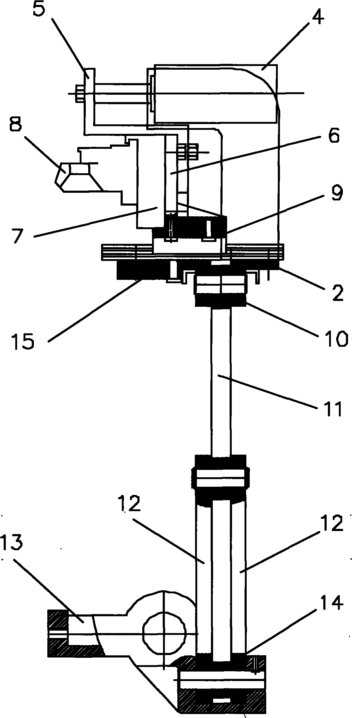
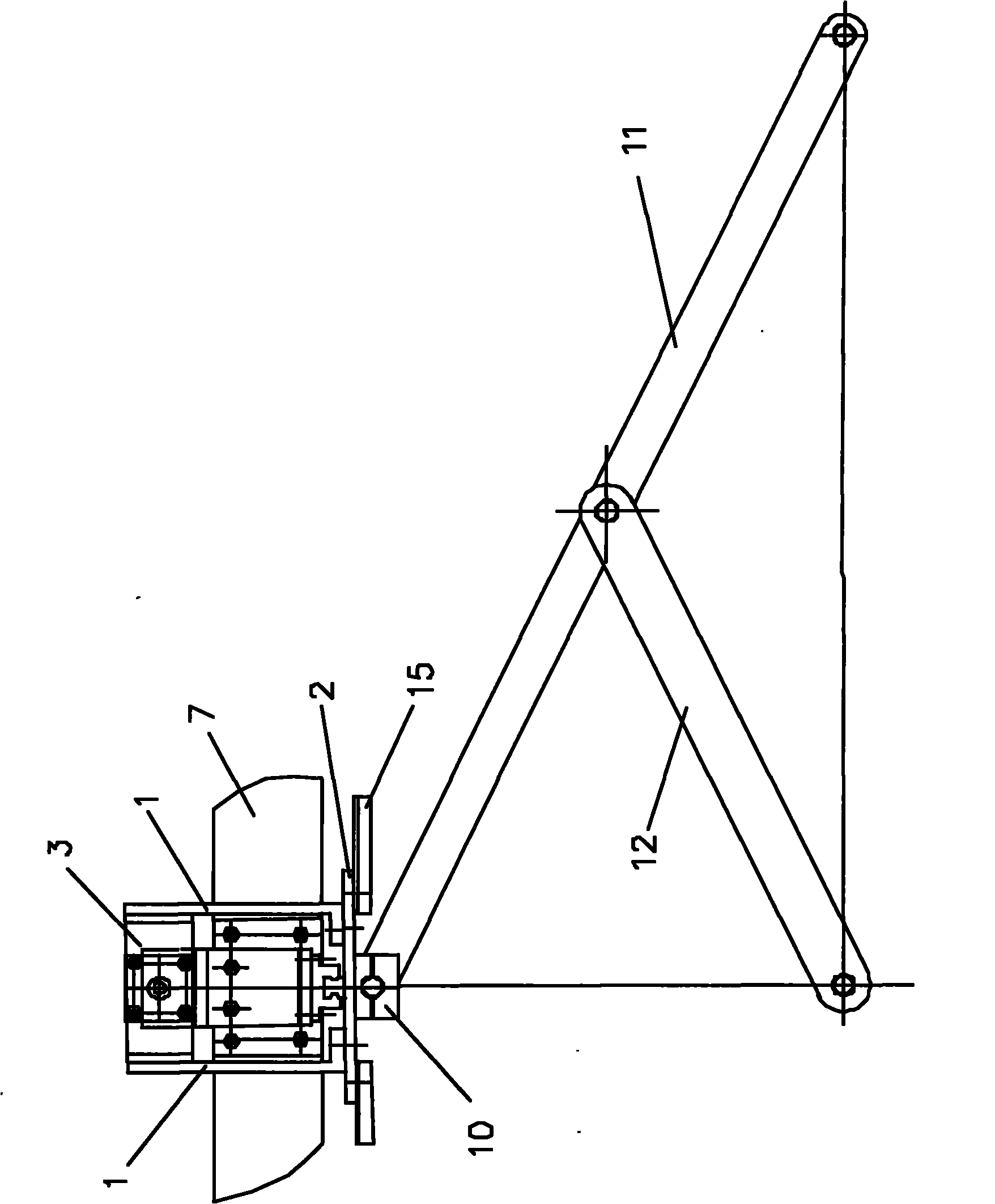
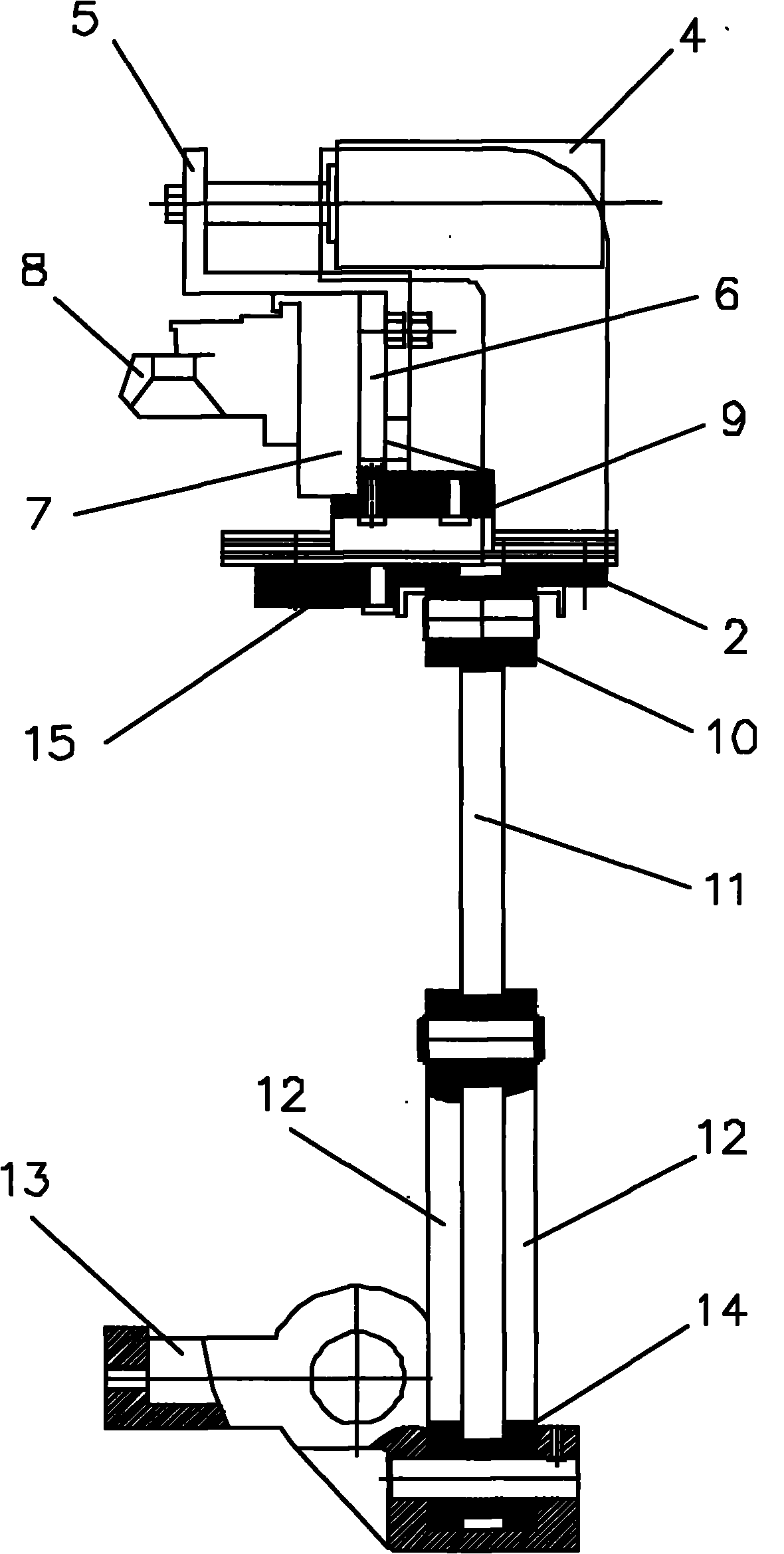
[0013] Such as figure 1 and figure 2 As shown, a moving device of a yarn spinning machine gripper of the present invention includes a vertical plate 1, a support plate 2, a cylinder seat 3, a cylinder 4, a push plate 5, an aluminum tube seat 6, a yarn gripper 7, and a gripper Device 8, rolling linear guide pair 9, bearing 10, long connecting rod 11, short connecting rod 12 and hanging pin 13. Riser 1 is two pieces, can be L-shaped. The two vertical plates 1 are arranged above the support plate 2 in correspondence with each other, the cylinder base 3 is fixedly connected to the two vertical plates 1 , and the cylinder base 3 is fixedly connected to the cylinder 4 . The connecting rod in the cylinder 4 is fixedly connected with one end of the push plate 5, the other end of the push plate 5 is fixedly connected with one side of the aluminum tube base 6, and the other side of the aluminum tube base 6 is fixedly connected with one side of the yarn holder 7, The other side of th...


PUM


Abstract

The invention relates to a moving device of a tube gripper of a spinning machine, which comprises a riser, a supporting plate, a cylinder seat, a cylinder, a push plate, an aluminum tube seat, a yarn holder, the tube gripper, a rolling linear guide rail pair, a support, a long connecting rod, a short connecting rod and a hanger. The rolling linear guide rail pair is arranged on the supporting plate, the aluminum tube seat is arranged on a slide block of the rolling linear guide rail pair, the yarn holder is fixed on the aluminum tube seat, the tube gripper is arranged on the yarn holder, the support is rotationally connected with one end of the long connecting rod, the middle part of the long connecting rod is rotationally connected with one end of the short connecting rod, the other end of the short connecting rod is rotationally connected on the hanger, the other end of the long connecting rod is glidingly connected in the hanger, and the hanger is fixedly connected on a wall board in the spinning machine. A connecting point of the support and the long connecting rod and a connecting point of the short connecting rod and the hanger are on the same vertical line. By using the technical scheme of the invention, the moving device has the advantages of simple operation, flexible translation, accurate tube gripping and placement and small occupied space, and fully meets the requirement of a textile mill production site.

Description

technical field [0001] The invention relates to a moving device in a yarn spinning machine, in particular to a moving device for a pipe gripper of a yarn spinning machine. Background technique [0002] The existing spinning machine is transformed into automatic collective doffing. Due to the large width of the frame model, the installation of the spun tube seat cannot be aligned with the spindle in the longitudinal direction, so the installation size of the spun tube seat is larger than the spindle installation size. When the installation size of the spinning tube seat is larger than that of the spindle, the tube grabber must add a translation step to grasp the tube, instead of just lifting and lowering to realize the empty bobbin and full bobbin between the spindle, the storage column and the spinning tube seat switch between positions. The translational translation of the existing pipe grabber is in the position of fewer spindles, and the lever swing translation is used, ...

Claims


Application Information

Patent Timeline
IPC IPC(8): D01H9/04D01H9/02
Inventor 许元成陆进
Owner NANTONG JINCHI MECHANICAL ELECTRIC
Why Eureka
Try Eureka