Automobile frame longitudinal beam detection and precise positioning device and detection method

An automobile frame, precise positioning technology, applied in the direction of measuring/indicating equipment, manufacturing tools, metal processing machinery parts, etc., to achieve precise positioning, ensure detection quality and detection speed, and have broad product market prospects.

Inactive Publication Date: 2015-11-11
CHANGCHUN INST OF TECH
View PDF3 Cites 0 Cited by
  • Summary
  • Abstract
  • Description
  • Claims
  • Application Information

AI Technical Summary

Problems solved by technology

[0006] The object of the present invention is to provide a precise positioning device for the detection and positioning of the longitudinal beam of the automobile frame, which solves the shortcomings of the current manual interpretation, overcomes various errors caused by manual detection, and can quickly and accurately detect the processing quality of the longitudinal beam of the automobile frame Whether it is qualified or not, the automatic detection function of the processing quality of the longitudinal beam of the automobile frame has been realized. The project technology is highly mature, and there is no technical risk. Its detection performance is efficient and accurate, which can meet the needs of the production site. Production efficiency is very important

Method used


Image

  • Automobile frame longitudinal beam detection and precise positioning device and detection method
  • Automobile frame longitudinal beam detection and precise positioning device and detection method
  • Automobile frame longitudinal beam detection and precise positioning device and detection method

Examples


Embodiment

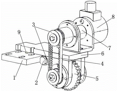
[0021] The connection plate 1 is connected with the motion platform of the CNC punch press to ensure that the device moves together with the longitudinal beam; the large synchronous pulley 5 is in contact with the timing belt 4 on the stationary platform of the CNC punch press to ensure that the device can collect when the longitudinal beam moves. The movement information of the longitudinal beam (the number of pulses of the encoder), the rotation information of the large synchronous pulley 5 pass through two small synchronous pulleys 3 and the synchronous belt 4, and the coupling 7 is connected with the encoder 8, so that the linear motion The information is converted into the number of pulses of the encoder 8, so as to obtain real-time information on the movement of the longitudinal beam for image acquisition of the longitudinal beam. During the movement of the longitudinal beam, the stationary platform on the CNC punching machine is not absolutely flat, and there are many un...


PUM


Abstract

The invention relates to an accurate positioning device for detecting a longitudinal beam of an automotive frame. The device consists of a connecting plate, a rotating shaft, two small synchronous belt pulleys, a synchronous belt, a large synchronous belt pulley, a support, a coupling, an encoder and a silk paper pad. The device is characterized in that: the connecting plate is connected with a motion platform of a computerized numerical control punching machine; the large synchronous belt pulley is contacted with a synchronous belt on a stationary platform of the computerized numerical control punching machine, and is connected with the two small synchronous belt pulleys and the synchronous belt; the coupling is connected with the encoder; the silk paper pad is arranged between the support and the connecting plate of the device; and the rotating shaft is arranged on the other side of the connecting plate. The device overcomes the disadvantages of the present artificial interpretation, eliminates various errors caused by artificial detection, can quickly and accurately detect whether the processing quality of longitudinal beams of automotive frames is qualified, realizes the function of automatically detecting the processing quality of the longitudinal beams of the automotive frames, can meet the requirements of production fields, and has a great significance for improving the detection level and production efficiency of automobile industry in China; the technical maturity of projects is high; technical risks are avoided; and the detection performance of the device is efficient and accurate.

Description

technical field [0001] The invention relates to a detection and precise positioning device and detection method for a longitudinal beam of an automobile frame, which are applied to the detection of a large-size flat piece. Background technique [0002] There are more than 200 holes that need to be processed on the longitudinal beam of the automobile frame. In the process of processing, the quality defects of incomplete hole processing often occur due to punches, drills broken or processing omissions. The frame longitudinal beams with the above-mentioned quality defects enter the production and assembly process, which will seriously affect the normal production order, disrupt the rhythm of the production process, and cause great economic losses to the enterprise. [0003] Since the positions of the holes on the longitudinal beams of automobile frames have no obvious distribution rules, the methods of detecting the number of target holes such as photoelectric sensors or magne...

Claims


Application Information

Patent Timeline
Patent Type & Authority Patents(China)
IPC IPC(8): B21C51/00B23Q17/20B23Q17/22B23Q17/24
Inventor 王华高金刚张爽王善刚王大宇于雷付胡代杨青山
Owner CHANGCHUN INST OF TECH
Why Eureka
Try Eureka