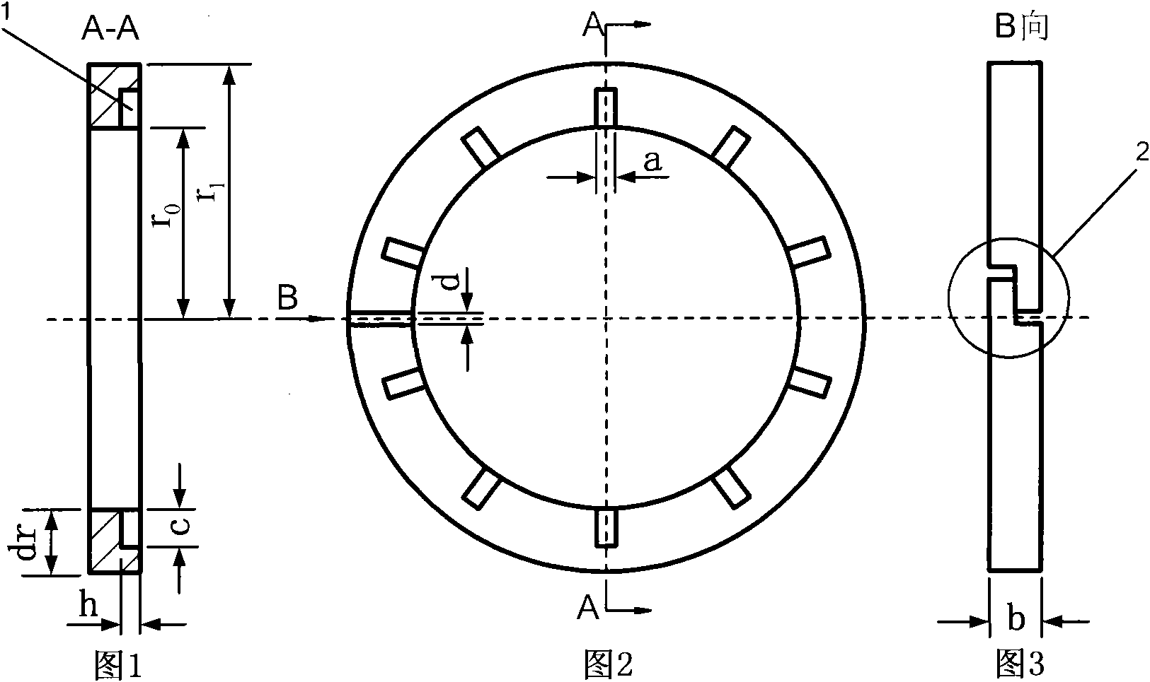
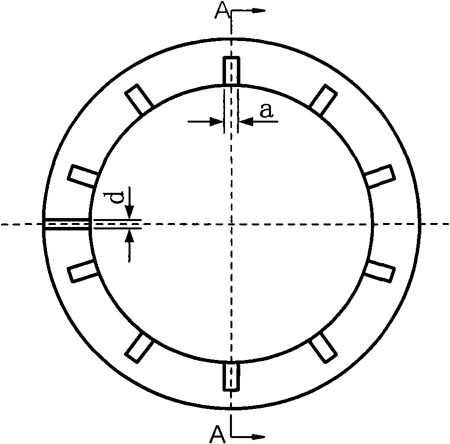
Sealing ring with isobathic rectangular groove on end surface

A rectangular groove and sealing ring technology, applied in the field of liquid rotary sealing parts, can solve the problems of rotary sealing ring failure, sealing end face wear, thermal cracking, etc., and achieve the effect of improving work performance and being easy to implement

Inactive Publication Date: 2010-10-20
BEIJING INSTITUTE OF TECHNOLOGYGY
View PDF2 Cites 10 Cited by
  • Summary
  • Abstract
  • Description
  • Claims
  • Application Information

AI Technical Summary

Problems solved by technology

When the PV value rises, the sealing end face of the rotating seal ring will experience rapid wear and thermal cracki

Method used


Image

  • Sealing ring with isobathic rectangular groove on end surface
  • Sealing ring with isobathic rectangular groove on end surface
  • Sealing ring with isobathic rectangular groove on end surface

Examples


Embodiment Construction

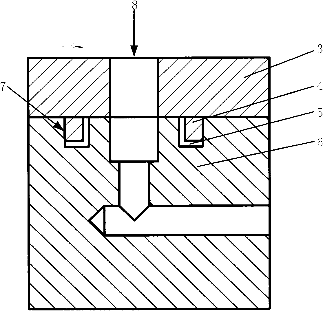
[0012] see Figure 4 , which shows the installation state of the rotary seal ring in the wet clutch. As shown in the figure, (8) in the figure is the oil inlet of the clutch. The oil inlet sleeve (3) is used to supply oil to the wet clutch, and the oil inlet sleeve is non-rotating; the oil distribution sleeve (6) is used to supply oil to the wet clutch. The piston cylinder of the clutch distributes oil, and the oil distribution sleeve rotates together with the clutch shaft; the outer circular surface of the oil distribution sleeve (6) has a sealing ring installation groove (5), and the rotating sealing ring is just installed in this groove. Before assembly, the oil inlet sleeve (3) and the oil distribution sleeve (6) need to be separated; then the rotating seal ring (4) should be stretched and inserted into the seal ring installation grooves on the outer circle of the oil distribution sleeve (6) (5), note that the side with the rectangular groove (1) on the seal ring (4) must...


PUM

PropertyMeasurementUnit
Widthaaaaaaaaaa

Abstract

The invention relates to a rotary sealing ring applied to a wet-type clutch. Dramatic abrasion is easy to occur on the traditional sealing ring under a high PV working condition, thereby resulting in failure of the sealing ring and further causing the wet-type clutch to lose the engagement function. By adopting a method for setting an isobathic rectangular groove on the end surface of the sealing ring, the invention provides sufficient lubricant medium for a friction working surface to produce dynamic pressure lubrication, thereby greatly improving the operating performance of the sealing ring. The method is simple and effective, is easy for promotion, and solves an important technical problem for the design of a high-speed and high-pressure wet-type clutch.

Description

technical field [0001] The invention belongs to a liquid rotary sealing part, more specifically a rotary sealing ring applied in a wet clutch. Background technique [0002] The allowable PV value of the rotary seal ring used in the current wet clutch is relatively low. When the PV value rises, the sealing end face of the rotating sealing ring will experience rapid wear and thermal cracking, resulting in failure of the rotating sealing ring, and indirectly causing the wet clutch to lose its bonding function. Therefore, without changing the size of the rotating sealing ring, if the working PV value of the rotating sealing ring can be increased, the working oil pressure and working speed of the wet clutch will also be improved, so the wet clutch can be arranged on the high-speed shaft, Optimize the layout of the internal components of the mechanical transmission. Contents of the invention [0003] The purpose of the present invention is to address the above problems, adopt ...

Claims


Application Information

Patent Timeline
IPC IPC(8): F16J15/16
Inventor 苑士华胡纪滨魏超刘丁华荆崇波李雪原尹旭峰彭增雄
Owner BEIJING INSTITUTE OF TECHNOLOGYGY
Why Eureka
Try Eureka