Petroleum gas steel bottle control valve

A technology of LPG and control valves, applied in the direction of control valves, valve details, valve devices, etc., can solve the problems of easy stealing, easy leakage, low inflation efficiency, etc., to avoid illegal inflation, ensure inflation quality, The effect of preventing air stealing

Inactive Publication Date: 2010-10-20
谭启纯
View PDF5 Cites 2 Cited by
  • Summary
  • Abstract
  • Description
  • Claims
  • Application Information

AI Technical Summary

Problems solved by technology

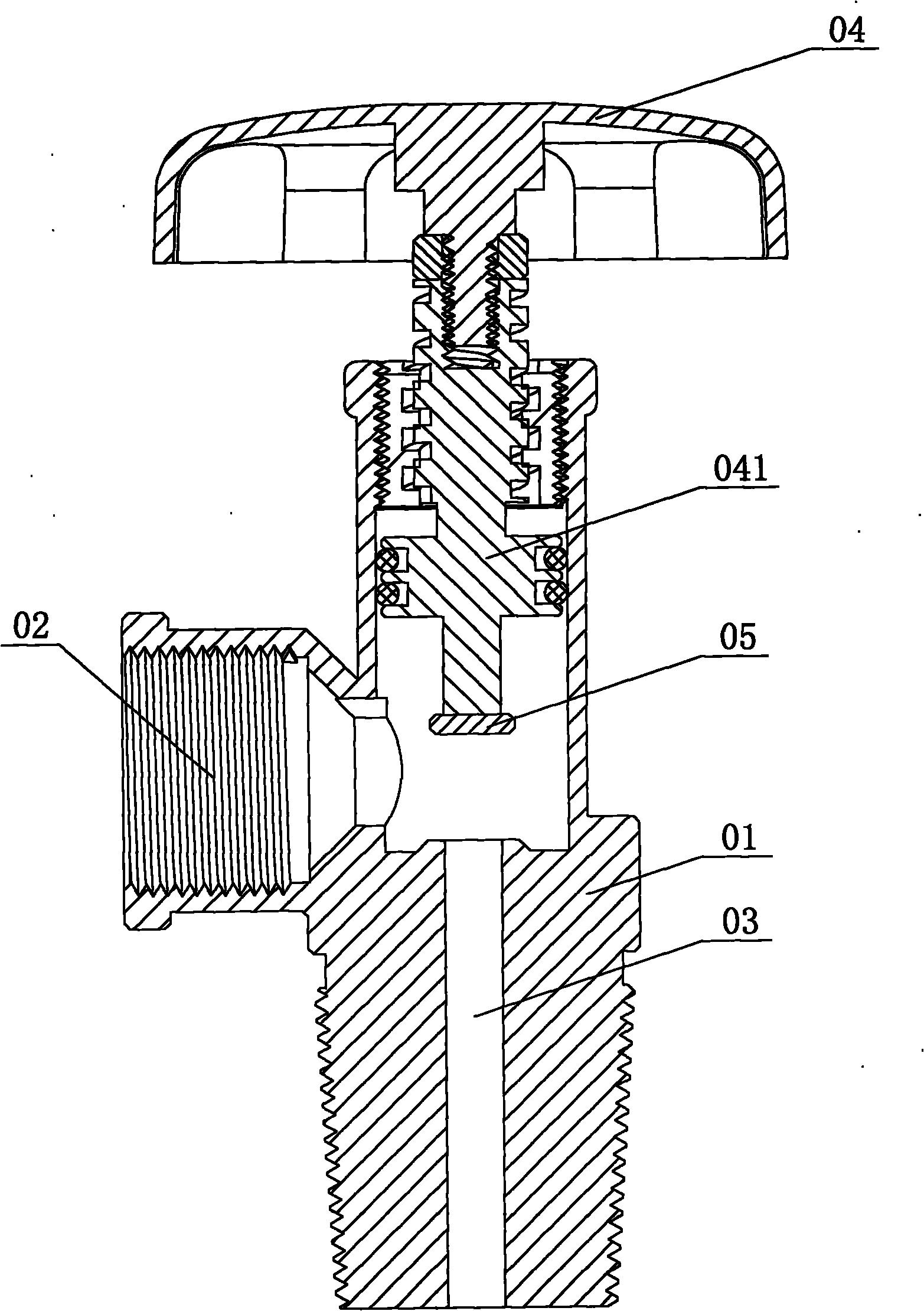
[0002] The structure of the existing liquefied petroleum gas cylinder control valve is as follows: figure 1 As shown, it is composed of valve body 01, connecting port 02, air channel 03, handwheel 04 and gasket 05 installed on the main shaft of the handwheel 041. By rotating the handwheel 04, the gasket 05 is controlled to rise and fall, thereby realizing air The switch of channel 03, you need to turn the hand wheel 04 when inflating, so that the gasket 05 rises, the air channel 03 is opened, insert the charging gun to fill the gas cylinder with liquefied petroleum gas, after completing the inflation, you must first turn the hand wheel 04, put The sealing gasket 05 descends and presses the outlet of the airway to close the airway 03, and then the inflation gun can be pulled out. The control valve with this structure has the following disadvantages: 1. The inflation steps are cumbersome and the inflation efficiency is very low; 2. If the sealing gasket is pressed The down pressure of the airway outlet is insufficient, and air leakage is prone to occur; 3. Sometimes during storage and transportation, the handwheel and the valve body will become loose, and air leakage will also occur; 4. It is easy to steal the gas in the cylinder. For liquefied petroleum gas, just turn the hand wheel to make the sealing gasket leave the airway outlet, and invert the steel cylinder to make the liquefied petroleum gas flow out; 5. It cannot prevent the occurrence of illegal inflation, and criminals can use any existing common inflatable gun. Fill it with liquefied petroleum gas

Method used


Image

  • Petroleum gas steel bottle control valve
  • Petroleum gas steel bottle control valve
  • Petroleum gas steel bottle control valve

Examples


Embodiment Construction

[0026] Now elaborate the present invention in conjunction with accompanying drawing:

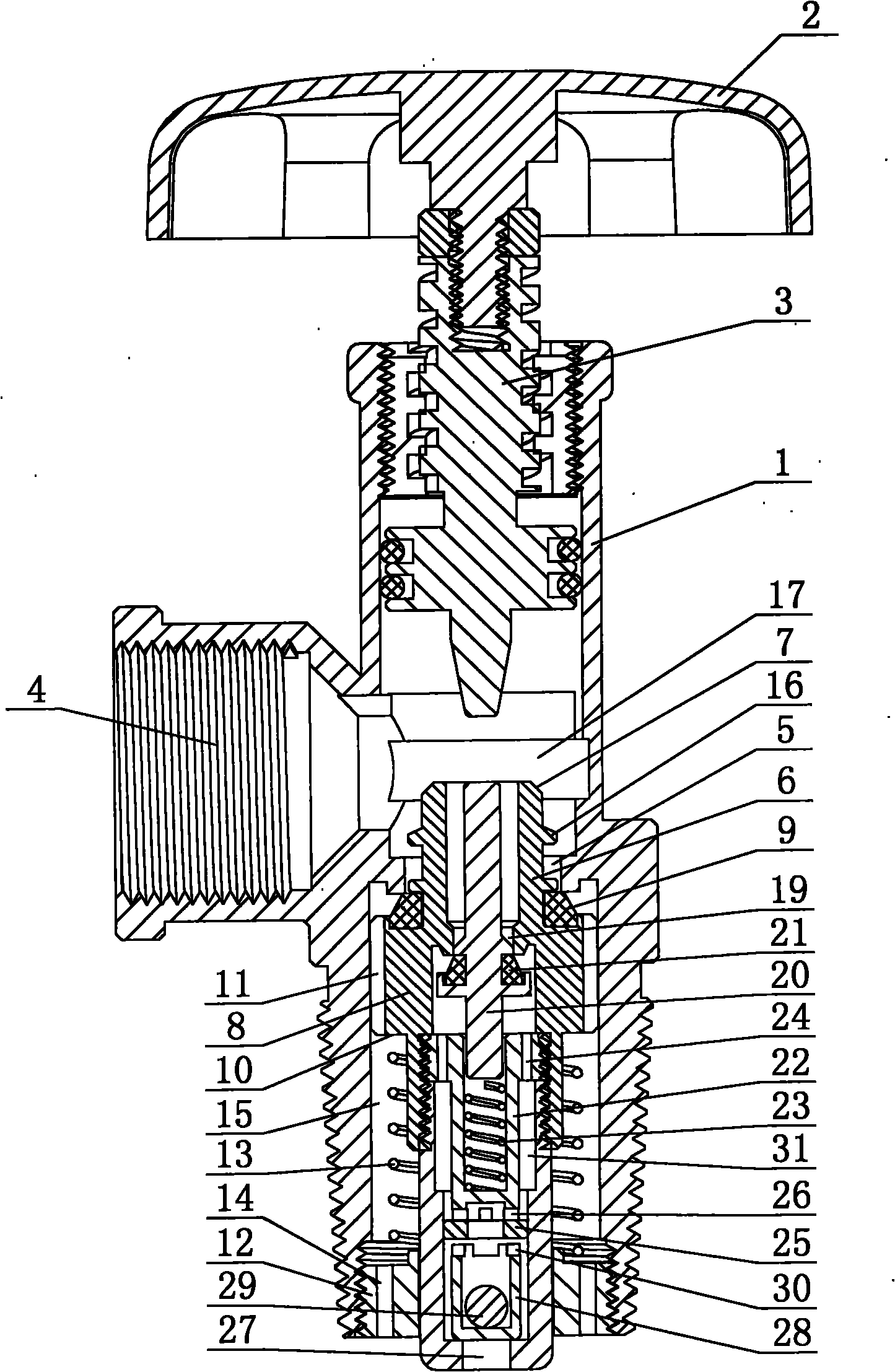
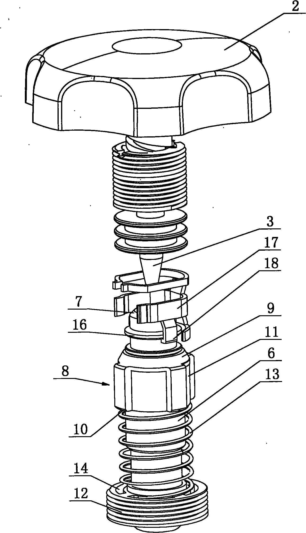
[0027] The petroleum gas cylinder control valve includes a hollow valve body 1, a handwheel 2, a handwheel rotating shaft 3 and a gas delivery port 4. The handwheel rotating shaft 3 is a lower pressure rod, and the lower outer peripheral surface of the hollow valve body 1 is processed with threads. Thread, the hollow valve body 1 is installed on the top of the LPG cylinder, and the first closing port 5 and the lifting sleeve 6 are arranged in the hollow valve body 1. The structure of the lifting sleeve 6 is as follows: Figure 10 As shown, the lifting sleeve 6 is divided into two parts, an upper cylinder 61 and a lower cylinder 62. The upper cylinder 61 and the lower cylinder 62 are connected together by threads, and the top of the lifting sleeve 6 extends upwards to the gas delivery port 4. And the top edge is processed with a guide chamfer 7, and a convex ring 8 is formed on the outer wall...


PUM


Abstract

The invention discloses a petroleum gas steel bottle control valve with quick gas filling and reliable sealing. The valve comprises a hollow valve body, a compression rod and a gas inlet; a first closing port is formed in the hollow valve body; a lifting sleeve with the resetting function is inserted into the hollow valve body; a gas filling passage for communicating the gas inlet with a petroleum gas steel bottle inner cavity is formed between the hollow valve body and the lifting sleeve; the outer wall of the lifting sleeve is provided with a first sealing ring in matched seal with the closing port; a second closing port and a lifting plunger piston which is matched with the compression rod and has the resetting function are arranged in the lifting sleeve; the lifting plunger piston is provided with a second sealing ring in matched seal with the second closing port; a gas outlet passage communicated with the petroleum gas steel bottle inner cavity is formed between the lifting sleeve and the lifting plunger piston; and the top of the lifting sleeve extends upwards to a gas outlet and the edge of the top is provided with a guide sliding chamfer angle.

Description

Technical field: [0001] The invention relates to a petroleum gas cylinder control valve. Background technique: [0002] The structure of the existing liquefied petroleum gas cylinder control valve is as follows: figure 1 As shown, it is composed of valve body 01, connecting port 02, air channel 03, handwheel 04 and gasket 05 installed on the main shaft of the handwheel 041. By rotating the handwheel 04, the gasket 05 is controlled to rise and fall, thereby realizing air The switch of channel 03, you need to turn the hand wheel 04 when inflating, so that the gasket 05 rises, the air channel 03 is opened, insert the charging gun to fill the gas cylinder with liquefied petroleum gas, after completing the inflation, you must first turn the hand wheel 04, put The sealing gasket 05 descends and presses the outlet of the airway to close the airway 03, and then the inflation gun can be pulled out. The control valve with this structure has the following disadvantages: 1. The inflati...

Claims


Application Information

Patent Timeline
Patent Type & Authority Applications(China)
IPC IPC(8): F16K15/18F16K31/60F16K35/00
Inventor 谭启纯
Owner 谭启纯
Why Eureka
Try Eureka