
Display driving method and display

A display driver and display technology, applied in static indicators, instruments, etc., can solve the problem of vertical straight lines on the screen, and achieve the effect of suppressing the pattern phenomenon

Active Publication Date: 2010-10-20
AU OPTRONICS CORP
View PDF6 Cites 22 Cited by
  • Summary
  • Abstract
  • Description
  • Claims
  • Application Information

AI Technical Summary

Problems solved by technology

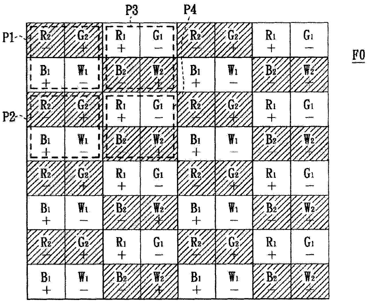
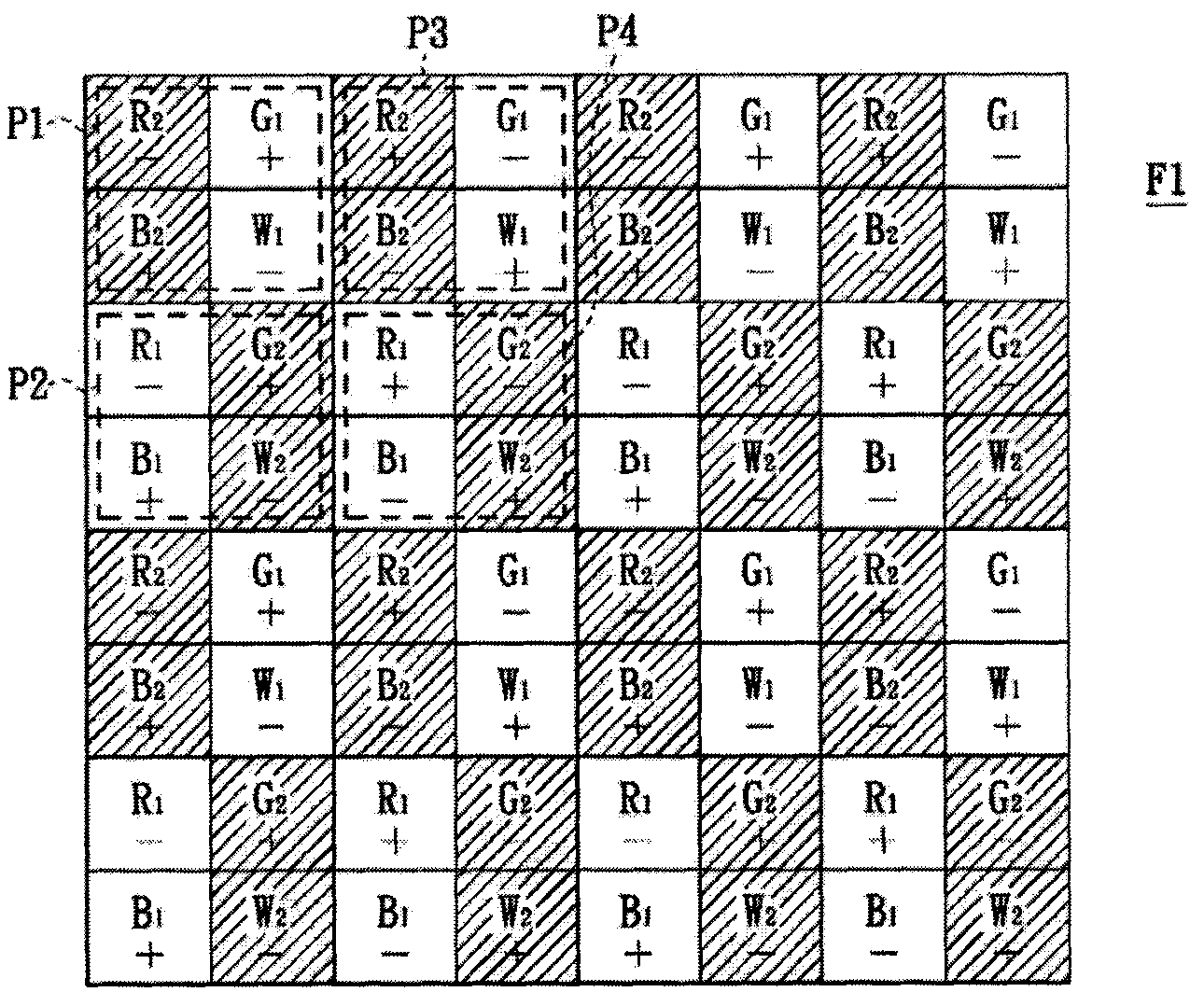
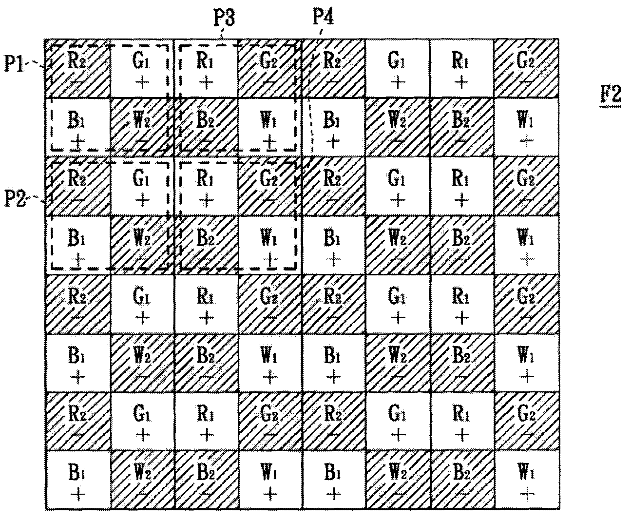
[0009] by Figure 1A and 1C In other words, the distribution of (A+1) grayscale value and A grayscale value will easily cause horizontal stripes when the screen is displayed, and the Figure 1B and 1D Generally speaking, the distribution of (A+1) grayscale value and A grayscale value will make the screen easy to cause vertical straight lines when displayed.

Method used


Image

  • Display driving method and display
  • Display driving method and display
  • Display driving method and display

Examples


Embodiment Construction

[0034] Please refer to figure 2 , which shows a schematic circuit block diagram of a display according to an embodiment of the present invention. In this embodiment, the display 200 includes a pixel array 202 , a data driving circuit 204 and a common voltage source 206 . The pixel array 202 is electrically coupled to the data driving circuit 204 and the common voltage source 206 , and the data driving circuit 204 transmits data signals to the pixel array 202 , and the common voltage source 206 provides a common potential to the pixel array 202 .

[0035] exist figure 2 In the example, taking the pixels P1, P2, P3 and P4 in the pixel array 102 as an example, the pixel P1 is adjacent to the pixels P2 and P3, and the pixel P4 is adjacent to the pixels P2 and P3. figure 2 16 pixels are taken as an example for illustration, but as those skilled in the art can easily know, the number of pixels is not limited thereto.

[0036]Each pixel P1, P2, P3 and P4 includes sub-pixels S1,...


PUM


Abstract

The invention discloses a display driving method which is suitable for being used on a display. The display comprises a pixel array and a data driving circuit, wherein the pixel array is provided with a first pixel, a second pixel, a third pixel and a fourth pixel. Each pixel comprises a first sub-pixel, a second sub-pixel, a third sub-pixel and a fourth sub-pixel. The display driving method comprises the following steps of: providing a data signal to the first pixel, the second pixel, the third pixel and the fourth pixel respectively; and secondly, displaying a second gray scale value sequentially by the sub-pixels with at least one color in a plurality of frames in the same frequency period and displaying a first gray scale value by the rest sub-pixels. The invention also discloses a display.

Description

technical field [0001] The invention relates to the field of display technology, and in particular to a display driving method and a display. Background technique [0002] Currently, liquid crystal displays can use frame rate control (Frame Rate Control) to increase the number of gray scales. Frame modulation can produce effects by time and space. The method of using time to generate frame modulation effects is called temporal dithering method (temporal dithering method), and the method of using spatial methods to generate frame modulation effects is called spatial dithering method. ). [0003] The spatial dithering method uses several frames per second to make each sub-pixel display different gray scale values ​​to mix different intermediate gray scale values. For example, in each frame, 1 / 4 of the sub-pixels display a grayscale value (A+1), and the remaining 3 / 4 subpixels display a grayscale value of A, that is, they can be mixed to produce an intermediate grayscale valu...

Claims


Application Information

Patent Timeline
Patent Type & Authority Applications(China)
IPC IPC(8): G09G3/20
Inventor 廖砚韬郑胜文
Owner AU OPTRONICS CORP
Learn More