Wireless terminal for reducing specific absorption rate peak and realization method thereof

A technology of wireless terminals and implementation methods, which is applied in the fields of printed circuits, transmission systems, and printed circuit manufacturing, and can solve problems such as the influence of antenna far-field radiation, the enhancement of wireless terminal electromagnetic radiation, and the reduction of wireless terminal SAR, so as to save costs and weaken SAR peak, space saving effect

Active Publication Date: 2010-10-20
ZTE CORP
View PDF2 Cites 11 Cited by
  • Summary
  • Abstract
  • Description
  • Claims
  • Application Information

AI Technical Summary

Problems solved by technology

[0002] With the rapid development of wireless communication technology, wireless terminals such as mobile terminals and data cards have been widely used, and it can also be found that the size of existing wireless terminals is becoming smaller and smaller, while increasing the difficulty of wireless terminal structure design , also brings another important problem: the electromagnetic radiation of wireless terminals to the human body is also enhanced
Although the above two schemes can achieve the purpose of reducing SAR, there is a common defect in the two schemes: among them, after the wave-absorbing material and / or radiation-proof layer are coated on the surface of the wireless terminal casing, the coated wave-absorbing material And / or the anti-radiation layer will absorb the electromagnetic wave emitted by the wireless terminal to the human body, but it will also absorb the useful signal radiated by the antenna in the form of electromagnetic wave, which will affect the communication quality of the wireless terminal; similarly, although the conductor reflector and shielding device can isolate The electromagnetic waves emitted to the human body will also isolate the useful signal radiated from the antenna and affect the communication quality of the wireless terminal
The above two solutions not only reduce the SAR of the wireless terminal, but also affect the communication performance of the wireless terminal. That is to say, the radiation to the human body in the near area of ​​the wireless terminal antenna is reduced, but the far-field radiation of the antenna is greatly affected. The wireless terminal cannot communicate smoothly, and the communication quality cannot be guaranteed

Method used


Image

  • Wireless terminal for reducing specific absorption rate peak and realization method thereof
  • Wireless terminal for reducing specific absorption rate peak and realization method thereof
  • Wireless terminal for reducing specific absorption rate peak and realization method thereof

Examples


Embodiment Construction

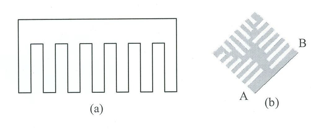
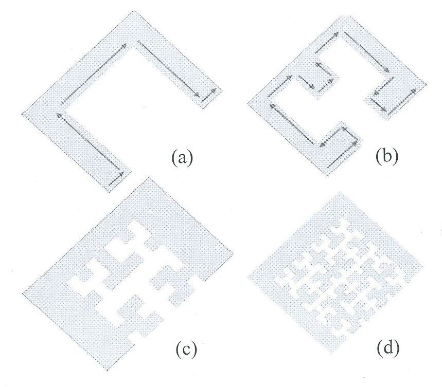
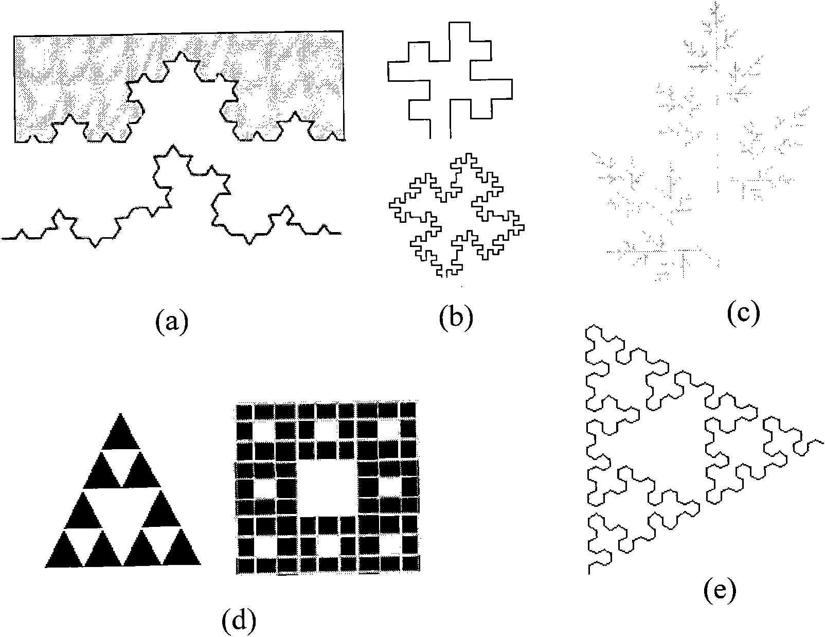
[0023] It is known from the prior art that the SAR peak of the wireless terminal comes from the joint contribution of the antenna conductor itself and the surface current induced on the metal surface near the antenna; N. Kuster's research also shows that the SAR peak generally appears on the metal ground of the antenna or PCB. Near the surface maximum local induced current. In addition, according to the antenna theory, the near field of the antenna is determined by the radiation superposition of each sub-current source of the induced current. The sub-current sources can form a local extremum of the electric field when the phase is consistent, which is the SAR peak value. Based on the current edge effect and The proximity effect can be obtained, and the surface current of the PCB generally gathers at the edge of the metal ground. Among them, the sub-current sources are small current sources that make up the induced current. In the research process, people usually divide a curre...


PUM


Abstract

The invention discloses a wireless terminal for reducing specific absorption rate (SAR) peak, which comprises a printed circuit board (PCB), wherein the fractal slots are arranged on the metal edge of the PCB and are used for disturbing the induced current distribution of the metal edge. The invention also discloses a realization method for reducing the SAR peak. Without affecting the communication quality of the wireless terminal, the wireless terminal and the method can reduce the SAR, has low production cost, and saves the structural space of the wireless terminal.

Description

technical field [0001] The present invention relates to a technology for reducing the Absorption Rate (SAR, Specific Absorption Rate) of a wireless terminal, in particular to a wireless terminal for reducing the SAR peak value and its implementation method. Background technique [0002] With the rapid development of wireless communication technology, wireless terminals such as mobile terminals and data cards have been widely used, and it can also be found that the size of existing wireless terminals is becoming smaller and smaller, while increasing the difficulty of wireless terminal structure design , It also brings another important problem: the electromagnetic radiation of wireless terminals to the human body is also enhanced. [0003] At present, the index to measure the electromagnetic radiation of the antenna to the human body is SAR, which refers to the energy absorption ratio of the wireless terminal electromagnetic wave. The specific meaning is: under the action of ...

Claims


Application Information

Patent Timeline
Patent Type & Authority Applications(China)
IPC IPC(8): H04B1/40H04M1/02H05K1/02
CPCH05K2201/09354H05K3/00H04B1/40H05K1/0224H04M1/02H05K1/0298H05K1/02H05K2201/09145Y10T29/49124
Inventor 张璐
Owner ZTE CORP
Why Eureka
Try Eureka