Energy dispersion buffer system

A buffer system and decentralized technology, applied in water conservancy projects, sea area projects, coastline protection, etc., can solve the problems of being exposed to the outside, endangering the safety of pier 1, etc., and achieve the effect of reducing the flow velocity of water

Inactive Publication Date: 2010-10-27
彭大雄 +2
View PDF0 Cites 8 Cited by
  • Summary
  • Abstract
  • Description
  • Claims
  • Application Information

AI Technical Summary

Problems solved by technology

Under normal circumstances, the bottom of the pier base 102 will be buried in the sand of the river bed to stabilize the pier 1. However, since there is no setting around the pier base 102 that can absorb waves or prevent sand from being excavated Therefore, when the turbulent water flow (especially after the heavy rain) continuously impacts the pier base 102, the sand and stones around the pier base 102 will be gradually hollowed out by the downward rolling water flow, causing the pier base 102 and even all The piles 101 are exposed outside, which endangers the safety of the pier 1

Method used


Image

  • Energy dispersion buffer system
  • Energy dispersion buffer system
  • Energy dispersion buffer system

Examples


Embodiment Construction

[0030] The present invention will be described in detail below in conjunction with the accompanying drawings and embodiments.

[0031] The aforementioned and other technical contents, features and effects of the present invention will be clearly understood in the following detailed description of the three preferred embodiments with reference to the drawings.

[0032] Before presenting a detailed description, it is noted that in the following description, similar elements are denoted by the same numerals.

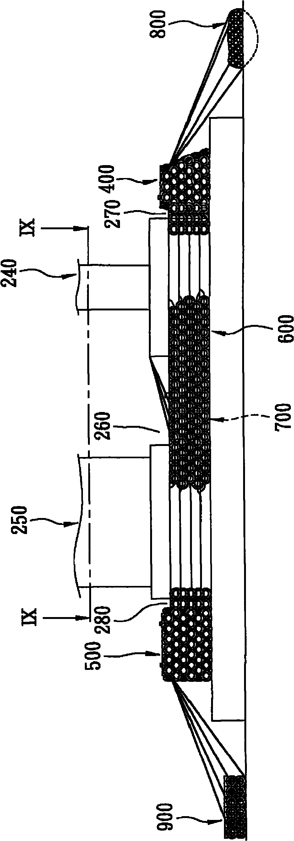
[0033] refer to figure 2 , the first preferred embodiment of the energy dispersive buffer system of the present invention is set at the upstream position of an upstream building 240 and the downstream position of a downstream building 250 and between the upstream building 240 and the downstream building 250, the The energy dispersion buffer system includes: a first buffer device 400 , a second buffer device 500 , two side protection devices 600 , an auxiliary gabion devic...


PUM


Abstract

The invention provides an energy dispersion buffer system, and comprises at least one buffer device, wherein the buffer device comprises at least three tyre pillar units, a round net unit, a filling unit and a cladding unit; the tyre pillar units are arranged at intervals and are respectively provided with a branch positioning pillar, a plurality of waste tyres and a cladding net; the waste tyres are arranged on the positioning pillar in a sleeved mode along the length direction of the positioning pillar and are stacked with each other; the cladding net clads the waste tyres; the round net unit comprises the tyre pillar units and defines out an accommodation space; the filling unit is filled in the accommodation space; the cladding unit is provided with a plurality of waste tyres cladded at the outside of the tyre pillar units, the round net unit and the filling unit; and the waste tyres are bound and fixed on the round net unit at least, and the adjacent waste tyres are bound and fixed with each other. The invention adopts the buffer device to eliminate the wave of the water flow, thereby reducing the water flow speed, and enabling the sand and stones around the base part of the building not to be hollowed out.

Description

technical field [0001] The invention relates to a buffer system, in particular to an energy dispersive buffer system which can prevent hollowing out around the bottom of a building set up in a water flow area. Background technique [0002] Such as figure 1 As shown, the existing bridge pier 1 built in the river generally has a plurality of piles 101 piled in the river bed and a pier seat 102 fixed on the piles 101 . Under normal circumstances, the bottom of the pier base 102 will be buried in the sand of the river bed to stabilize the pier 1. However, since there is no setting around the pier base 102 that can absorb waves or prevent sand from being excavated Therefore, when the turbulent water flow (especially after heavy rain) continuously impacts the pier base 102, the sand and stones around the pier base 102 will be gradually hollowed out by the downward rolling water flow, causing the pier base 102 and even all The piles 101 are exposed outside, which endangers the sa...

Claims


Application Information

Patent Timeline
Patent Type & Authority Applications(China)
IPC IPC(8): E02B3/20E02B8/06
Inventor 彭大雄彭光谦彭光聪
Owner 彭大雄
Why Eureka
Try Eureka