Supercharge Your Innovation With Domain-Expert AI Agents!

Plastic lamp holder

A lamp cap and plastic part technology, applied in the field of plastic parts lamp caps for lighting, can solve the problems of flux outflow, lamp cap corrosion and rust, affecting product quality, etc., and achieve the effect of reducing pollution and saving costs

Inactive Publication Date: 2010-10-27
段新杰
View PDF0 Cites 3 Cited by
  • Summary
  • Abstract
  • Description
  • Claims
  • Application Information

AI Technical Summary

Problems solved by technology

[0003] At present, the lighting lamp holders used by electric light sources are made of nickel-plated iron or galvanized lamp holders. In the production process, the lamp holders are screwed on the plastic parts of the energy-saving lamps and combined with each other. The use of this lamp holder has the following defects: first The equipment is complicated and costly when manufacturing the lamp cap, and at the same time, the gold-plating process is used, which causes great pollution to the environment; secondly, the process of assembling energy-saving lamps using this lamp cap is cumbersome, and the production process of screwing the lamp cap, welding the lamp cap, and riveting the lamp cap is required. , not only affects the output but also affects the quality of the product; thirdly, the welding connection method is used in the production process of the welding lamp cap, which will easily cause the flux in the solder wire to flow out to the surface of the lamp cap during operation, thereby causing corrosion and rust on the lamp cap and affecting the product. The quality of the lamp holder is high, although the welding-free environmentally friendly lamp holder is also used today, but the problem has not been fundamentally solved. Therefore, how to change the production process of the lamp holder is a new topic in the energy-saving lamp industry.

Method used


Image

  • Plastic lamp holder
  • Plastic lamp holder

Examples


Embodiment Construction

[0012] Further illustrate the specific embodiment of the present invention below in conjunction with accompanying drawing

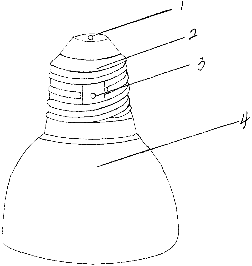
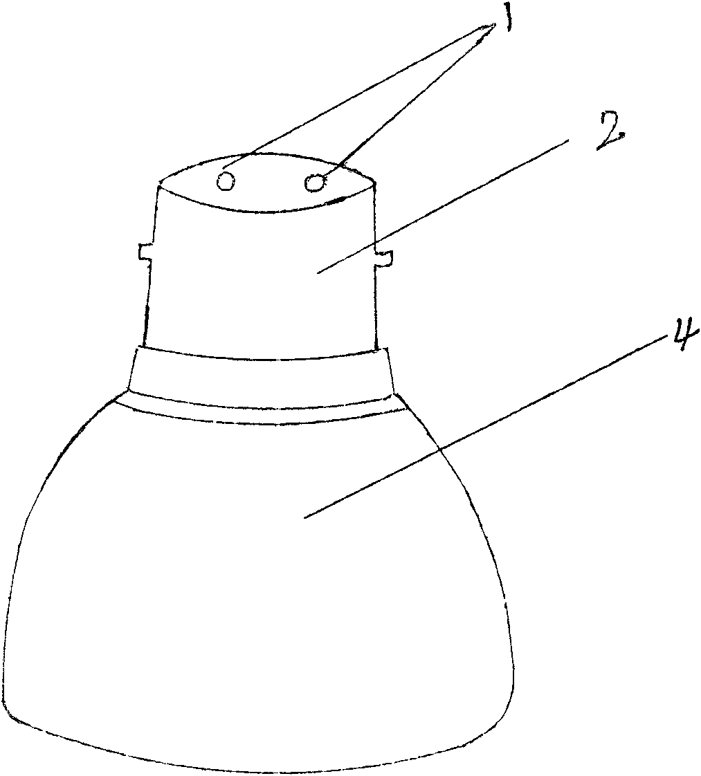
[0013] The key technology of the present invention is to directly combine the lamp holder and the upper plastic parts of the energy-saving lamp with each other, so in the specific implementation, only one injection mold can be installed to directly combine the lamp holders of various types and the upper plastic parts. , the plastic lamp cap after injection molding is very simple in production and operation. For the E-type lamp cap, because its principle is a spiral type, the upper point and the side point are connected to the power connection point, so only It is necessary to pass one wire on the circuit board through the small hole at the top of the lamp head and rivet it, and the other wire should pass through the small hole on the waist of the lamp head and rivet it, thus completing the wire The operation process of connecting with the lamp head; simil...


PUM


Abstract

The invention aims at providing an energy-saving plastic lamp holder. An injection mold which is capable of injecting the lamp holder and a plastic piece on an energy-saving lamp together is arranged according to E40, E27, E26, E14 and B22 type lamp holders which are conventionally used internationally and domestically, so that the lamp holder and the plastic piece on the energy-saving lamp can be combined and injected into a whole. Then a pore is reserved in the midst of the top of the molded plastic lamp holder and in the middle waist part of the lamp holder respectively for the E type lamp holders, and is used for connecting a lead wire on a circuit board of the energy-saving lamp with an input power supply; two pores are reserved on the top of the molded plastic lamp holder for the B type lamp holder, and are used for connecting two lead wires on the circuit board of the energy-saving lamp with positive and negative poles of the input end of a power supply, so that the novel energy-saving plastic lamp holder. After the novel plastic lamp holder is adopted, both the qualification rate of products and productivity effect can be improved on producing process and producing link, so the lamp holder is a great technical revolution for lighting industry.

Description

[0001] Field [0002] The invention relates to a plastic lamp cap for lighting, in particular to a plastic lamp cap for energy-saving lamp lighting. Background technique [0003] At present, the lighting lamp holders used by electric light sources are made of nickel-plated iron or galvanized lamp holders. In the production process, the lamp holders are screwed on the plastic parts of the energy-saving lamps and combined with each other. The use of this lamp holder has the following defects: first The equipment is complicated and costly when manufacturing the lamp cap, and at the same time, the gold-plating process is used, which causes great pollution to the environment; secondly, the process of assembling energy-saving lamps using this lamp cap is cumbersome, and the production process of screwing the lamp cap, welding the lamp cap, and riveting the lamp cap is required. , not only affects the output but also affects the quality of the product; thirdly, the welding connection...

Claims


Application Information

Patent Timeline
IPC IPC(8): F21S2/00H01J5/50
Inventor 段新杰
Owner 段新杰
Features
  • R&D
  • Intellectual Property
  • Life Sciences
  • Materials
  • Tech Scout
  • Unparalleled Data Quality
  • Higher Quality Content
  • 60% Fewer Hallucinations
Learn More