Cable mechanical de-icing device

A technology for cable machinery and deicing wheels, which is applied in the installation of cables, motor vehicles, electrical components, etc., can solve the problems of inconvenient operation and complex structure, and achieve the effects of convenient portability, simple operation and easy manufacturing.

Inactive Publication Date: 2010-10-27
GUILIN UNIV OF ELECTRONIC TECH
View PDF3 Cites 31 Cited by
  • Summary
  • Abstract
  • Description
  • Claims
  • Application Information

AI Technical Summary

Problems solved by technology

[0008] At present, some mechanical deicing solutions have appeared, but

Method used


Image

  • Cable mechanical de-icing device
  • Cable mechanical de-icing device
  • Cable mechanical de-icing device

Examples


Embodiment Construction

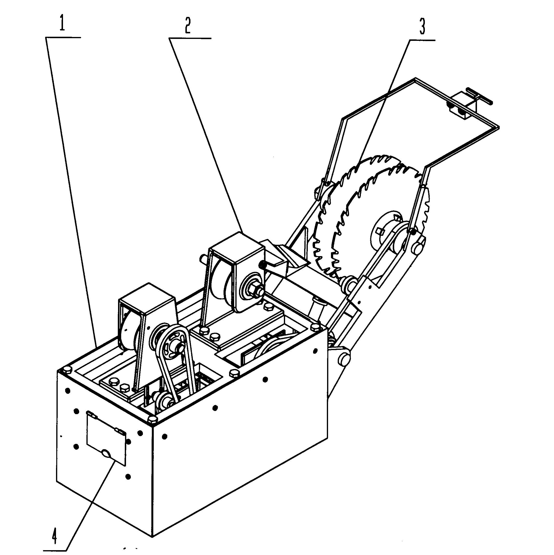
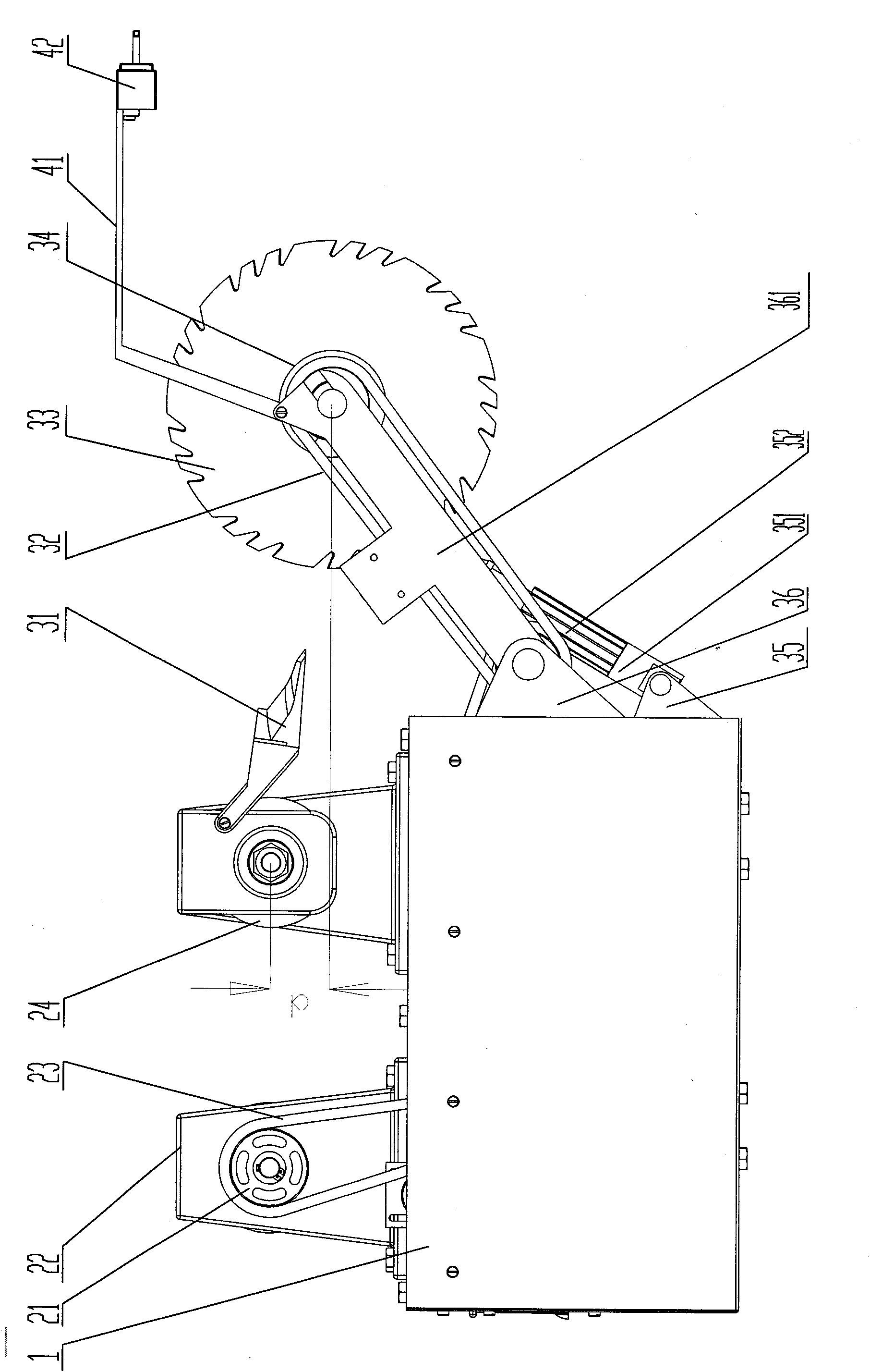
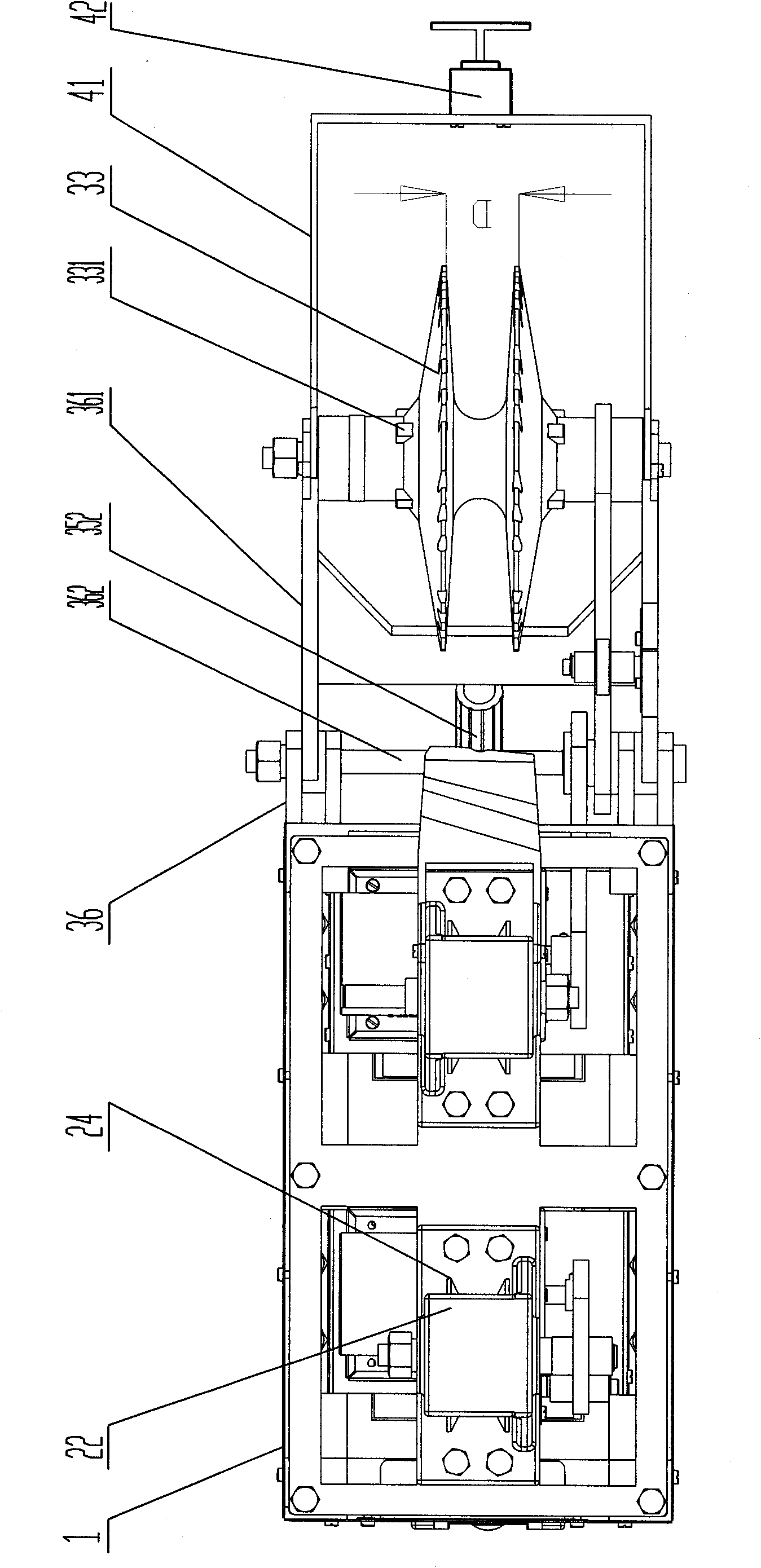
[0029] The overall structure of the embodiment of the cable mechanical deicing device is as follows: Figures 1 to 4 As shown, it includes a main body frame 1, a running mechanism 2, a deicing mechanism 3, a power mechanism and a control mechanism 4.

[0030] Described walking mechanism comprises hanger 22, road wheel 24, road wheel shaft and road chain wheel 21, and main frame 1 is the frame of cuboid. like Figure 5Shown, 2 front and rear hangers 22 are vertically fixed on the top surface of the main frame 1 through bolts, and 1 pair of walking wheel shafts and walking wheels 24 are installed on each hanger 22 . The walking wheel axle is rotatably installed on the hanger 1 through the bearing, and the walking wheel 24 is fixedly installed on the walking wheel axle by a key. The walking wheel axles on the front and back 2 hangers 22 are parallel. The traveling wheel 24 is a V-shaped grooved wheel, the front and rear 2 traveling wheels 24 are identical and the center planes...


PUM

PropertyMeasurementUnit
Widthaaaaaaaaaa
Diameteraaaaaaaaaa

Abstract

The invention discloses a cable mechanical de-icing device. Two hanging frames of the traveling mechanism are fixed on the top surface of a main body frame, and traveling wheels and traveling wheels of V type groove wheel are respectively on the hanging frames. A traveling chain wheel is fixedly mounted on the outside of the rear traveling wheel. A rear end of an H shaped bracket of the de-icing device is articulated with the main body chassis; a de-icing wheel shaft, a double-couple de-icing device, and a de-icing chain wheel; and the outer edge of the de-icing wheel is a de-icing tooth. A middle transverse rod of the H shaped bracket is supported by upper and lower support rods connected with a screw assembly in an inclined manner, so that the pitch angle of the de-icing wheel can be adjusted. An outer end of a hub of the de-icing wheel is provided with a convex ram. An ice scoop is mounted in front of the front hanging frame. Motors and a storage battery are fixed at the bottom of the main body frame. The power is transmitted by the chain wheels and the chains. The control mechanism is a control box, and a servo controller therein is connected with two motors to adjust the traveling speed of the device and the rotation speed of the de-icing wheel. An obstacle sensor connected with the control box is arranged in front of the bracket. The device is adapted to the de-icing work of the circular-section common high voltage transmission line below 110kV. The device has simple structure, easy operation and convenient portability.

Description

(1) Technical field [0001] The invention relates to auxiliary equipment technology for electric power transmission lines, in particular to a cable mechanical deicing device. (2) Background technology [0002] Ice and snow on transmission lines often cause accidents such as line tripping, disconnection, pole down, conductor galloping, insulator flashover, and communication interruption. Russia, Canada, the United States, Japan, the United Kingdom, Finland, Iceland and my country have all caused safety accidents due to icing of transmission lines, which have brought huge economic losses. Therefore, ice and snow disasters have become a common problem faced by power grids in many countries around the world. [0003] The short-circuit electrothermal deicing method is a relatively mature and effective means of deicing the power grid under current circumstances. However, there are many drawbacks in the short circuit ice melting method. [0004] First of all, it is necessary to ad...

Claims


Application Information

Patent Timeline
IPC IPC(8): H02G7/16B61B7/06B62D57/02
Inventor 李雪梅唐夏翔闫凡章
Owner GUILIN UNIV OF ELECTRONIC TECH
Why Eureka
Try Eureka