Electromagnetic compatibility optimizing method for receiver in targeted frequency ranges

A technology of electromagnetic compatibility and optimization method, applied in the direction of electrical components, transmission systems, etc., can solve the problem of ignoring the priority relationship, etc., to achieve the effect of improving efficiency

Active Publication Date: 2010-10-27
BEIHANG UNIV
View PDF3 Cites 21 Cited by
  • Summary
  • Abstract
  • Description
  • Claims
  • Application Information

AI Technical Summary

Problems solved by technology

This method isolates the cross-linking characteristics between multiple de

Method used


Image

  • Electromagnetic compatibility optimizing method for receiver in targeted frequency ranges
  • Electromagnetic compatibility optimizing method for receiver in targeted frequency ranges
  • Electromagnetic compatibility optimizing method for receiver in targeted frequency ranges

Examples


Embodiment

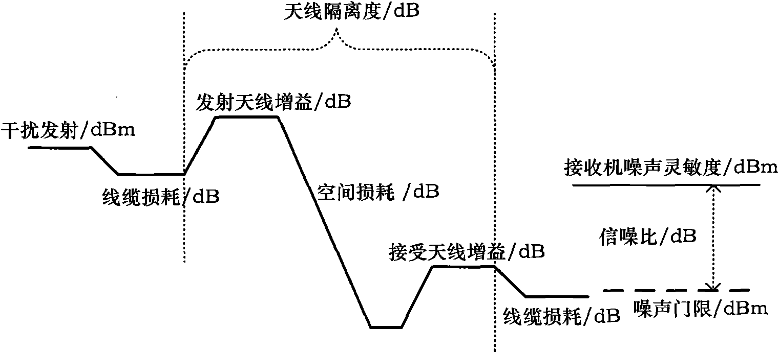
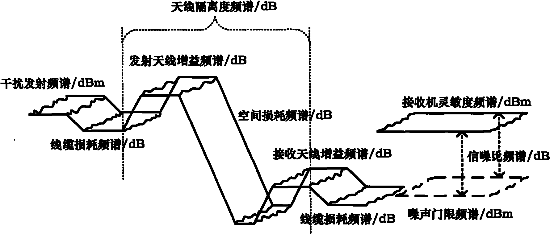
[0047] In a system formed by A equipment, B equipment, C equipment and receiver, it is assumed that the three equipment A, B, and C will cause potential interference to the receiver, and A is obtained in the simulation (ADS simulation software and FEKO simulation software). The equivalent noise curves of the three devices of , B, and C at the input port of the receiver, take the 1GHz, 1.5GHz, 2GHz, 2.5GHz, 3GHz, 3.5GHz, 4GHz, 4.5GHz, 5GHz, 5.5GHz, 11 frequency points including 6GHz. Combine the equivalent noise curves of the three devices A, B, and C to obtain the system equivalent noise curve, and compare it with the noise threshold curve of the receiver to determine the frequency band where the receiver is interfered and determine its dominant interference source. As shown in Table 1:

[0048] It can be seen from the above table that the system interferes with the receiver at four frequency points of 1GHz, 2.5GHz, 3.5GHz, and 5.5GHz, and these interferences come from equip...


PUM


Abstract

The invention discloses an electromagnetic compatibility optimizing method for a receiver in targeted frequency ranges. A plurality of interference devices and a width-band receiver are associated by using simulation software and the simulation computing power of a computer, and comprehensive consideration is given to the interference characteristic of each interference device, the interfered characteristic of the receiver and the spatial isolation degree so as to extract an interference leading source; and the interference leading source is used to systematically perform targeted electromagnetic compatibility optimization on the out-of-band emission of the interference devices, the spatial isolation degree of antennae and the interfered threshold of the wide-band receiver according to the priority. The method defines the optimization target and improves the optimization speed on the premise of ensuring the optimization effect.

Description

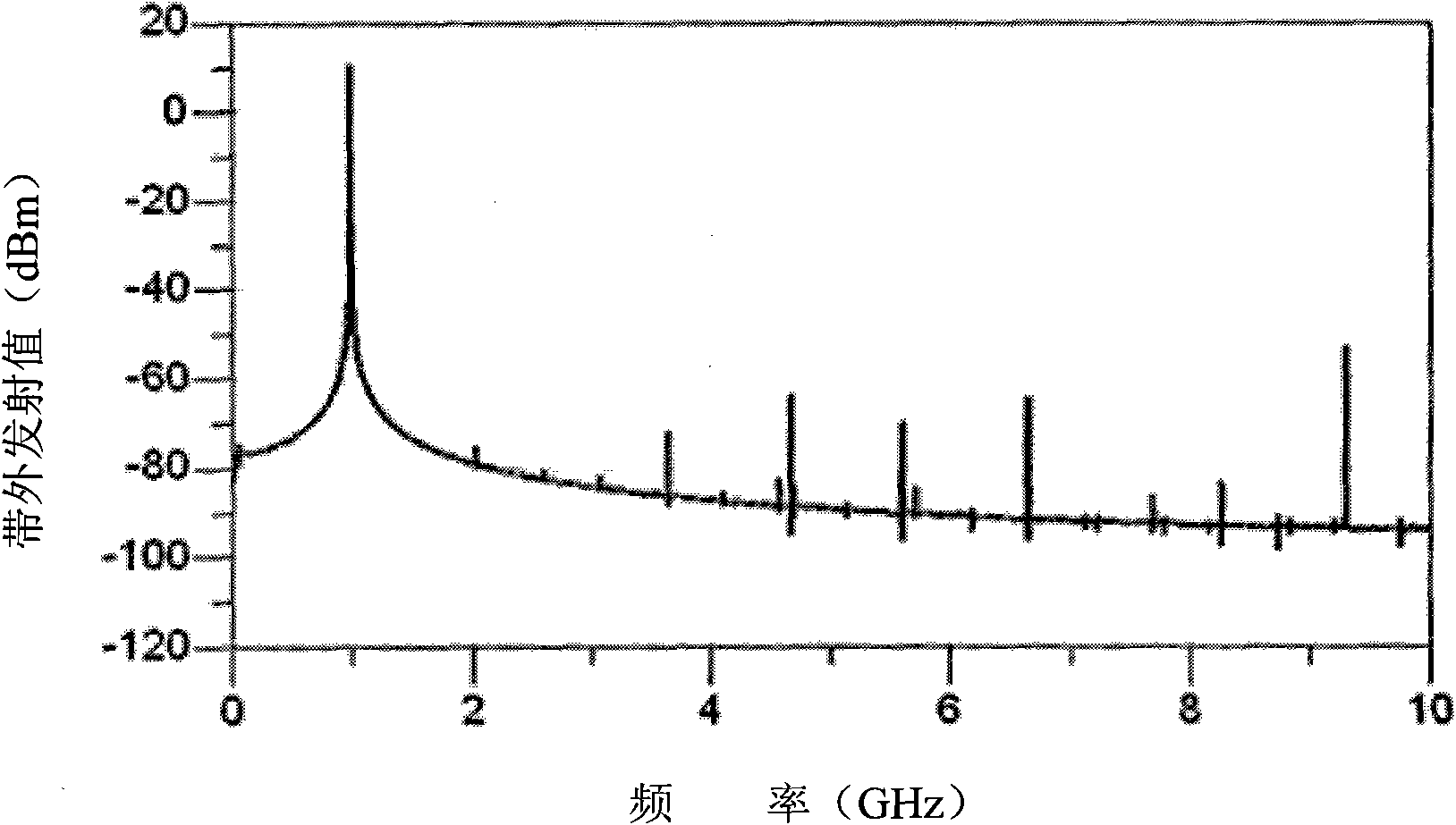
technical field [0001] The invention relates to an electromagnetic compatibility optimization method, in particular to an electromagnetic compatibility optimization method for wideband receivers under the electromagnetic interference environment of multiple devices. Background technique [0002] With the development of communication technology, ultra-wideband electronic technology, and the improvement of weapons and equipment requirements, the number of electronic devices required in the same space is increasing, and the cross-linking coupling between electronic devices is also more complicated. Every additional frequency-using device will cause potential electromagnetic interference to the ultra-wideband receiver and bring hidden dangers of electromagnetic compatibility. [0003] Due to the out-of-band emission of frequency equipment, antenna sidelobe effects, and electromagnetic induction of the body itself, even a system with good frequency planning and standardized anten...

Claims


Application Information

Patent Timeline
IPC IPC(8): H04B1/06H04B1/10
Inventor 陈文青倪子楠白天明刘柯王方明黄陶苏东林
Owner BEIHANG UNIV
Why Eureka
Try Eureka