
Method for realizing rapid optical cable termination by adopting standardized terminal fitting

A terminal connector, standard optical fiber technology, applied in the field of communication

Active Publication Date: 2011-12-28
CHINA UNITED NETWORK COMM GRP CO LTD
View PDF4 Cites 0 Cited by
  • Summary
  • Abstract
  • Description
  • Claims
  • Application Information

AI Technical Summary

Problems solved by technology

[0003]The biggest disadvantage of the existing splicing process is:
[0007]d. The quality of the end of the optical cable is randomly determined by the on-site process level, and the quality of the end of the optical cable is unstable

Method used


Image

  • Method for realizing rapid optical cable termination by adopting standardized terminal fitting
  • Method for realizing rapid optical cable termination by adopting standardized terminal fitting
  • Method for realizing rapid optical cable termination by adopting standardized terminal fitting

Examples


Embodiment Construction

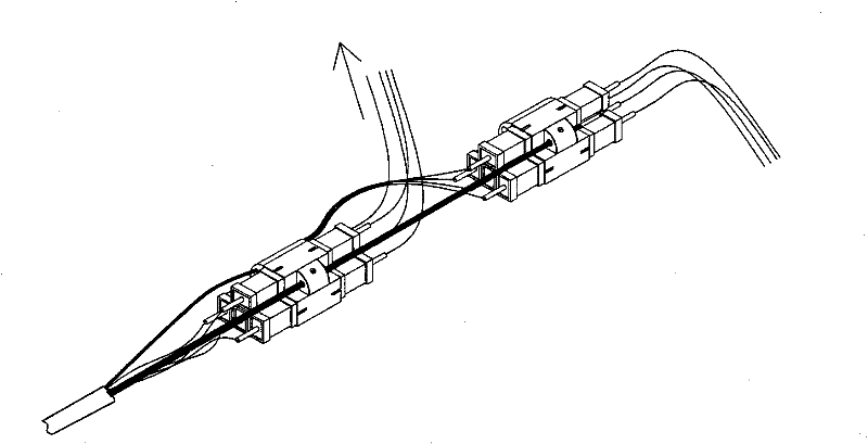
[0028] see figure 1 , the method for quickly terminating an optical cable of the present invention adopts an optical cable section with a joint, and cooperates with a terminal optical fiber connector through a standardized optical fiber joint at both ends of the optical cable section to realize rapid connection of the optical cable.

[0029] Wherein, the optical cable section with joints is provided with standardized optical fiber joints connected to the fiber core at both ends of the common optical cable section. Standardized optical fiber connectors can be selected to use SC connectors, FC connectors or LC connectors as required. Typical values ​​such as 500 meters, 1000 meters, 1500 meters and 2000 meters are used for the cable section.

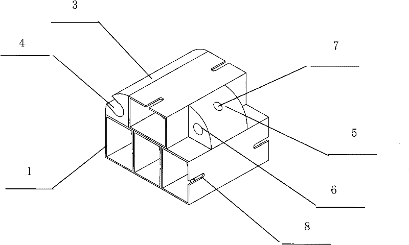
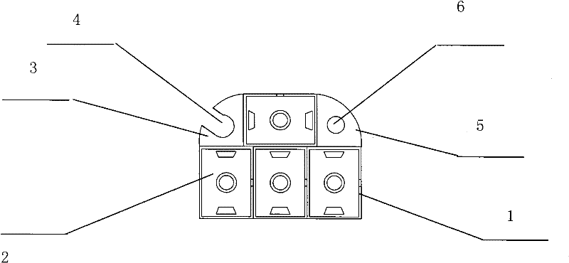
[0030] The above-mentioned terminal optical fiber connector includes two parts: a box body and a standard optical fiber connector fixedly arranged in the box body. Since the currently commonly used communication optical cables are 4, 8,...


PUM


Abstract

The invention provides a method for realizing rapid optical cable termination by adopting a standardized terminal fitting, belonging to the technical field of communication. In the method, an optical cable segment with joints is adopted, and standardized fiber joints at two ends of the optical cable segment are matched with a terminal fiber connector to realize rapid connection or optical path adjustment of an optical link, thereby avoiding a complex optical cable on-site termination process, greatly simplifying the optical cable pavement and connection procedures, saving labor and materials and lowering the optical cable connection costs. The quality of the finished optical cable segment is guaranteed by manufacturers, thereby avoiding the condition that the connection quality is randomly decided by the on-site process level and ensuring the connection quality of optical cables.

Description

technical field [0001] The invention belongs to the technical field of communication, and relates to a method for realizing the termination of optical cables, in particular to a method for realizing rapid termination of optical cables by adopting standardized terminal joints. Background technique [0002] The development of communication services and technologies requires the laying of optical cables in every corner of the city and countryside almost every day. At the same time, the newly laid optical cables are connected to related communication equipment through complex optical cable splicing technology to achieve fast and stable optical communication. The existing optical cable splicing process is to lay optical cables between two or more communication equipment rooms, and then carry out on-site optical cable termination in each equipment room, that is, to weld each core of the optical cable to a pigtail in the optical cable terminal box Through, and finally communicate w...

Claims


Application Information

Patent Timeline
Patent Type & Authority Patents(China)
IPC IPC(8): G02B6/44
Inventor 张永红
Owner CHINA UNITED NETWORK COMM GRP CO LTD
Learn More