Device for mutual locking of two switches, especially circuit breaker

A circuit breaker and switch technology, which is applied to the parts of protection switches, electric switches, protection switches, etc., can solve the problems of manufacturing tolerances and huge wear, and achieve the effect of compact implementation

Inactive Publication Date: 2010-11-10
SIEMENS AG
View PDF4 Cites 13 Cited by
  • Summary
  • Abstract
  • Description
  • Claims
  • Application Information

AI Technical Summary

Problems solved by technology

Deviations are only possible within very narrow tolerance ranges, which leads to a huge sensitivity to manufacturing tolerances and wear

Method used


Image

  • Device for mutual locking of two switches, especially circuit breaker
  • Device for mutual locking of two switches, especially circuit breaker
  • Device for mutual locking of two switches, especially circuit breaker

Examples


Embodiment Construction

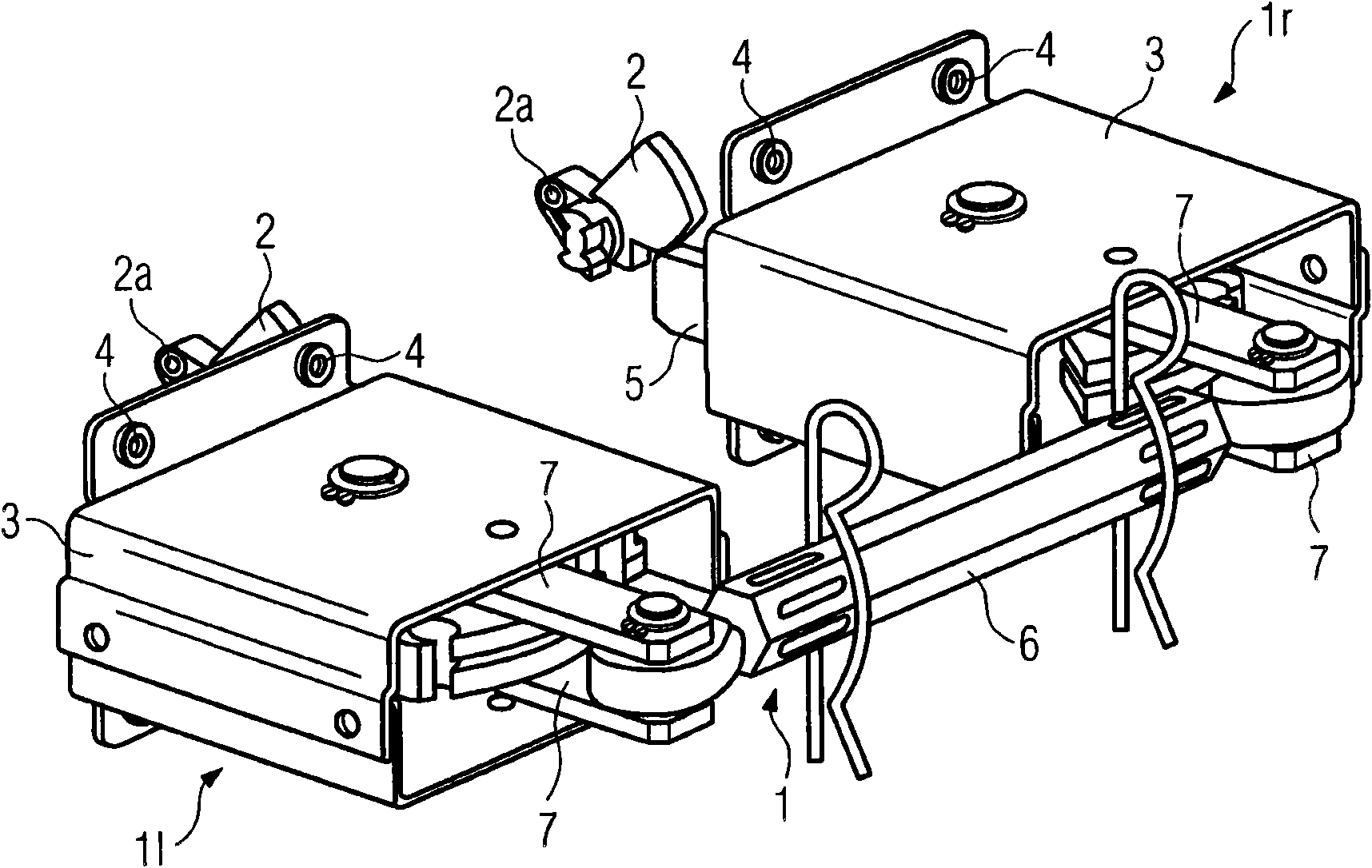
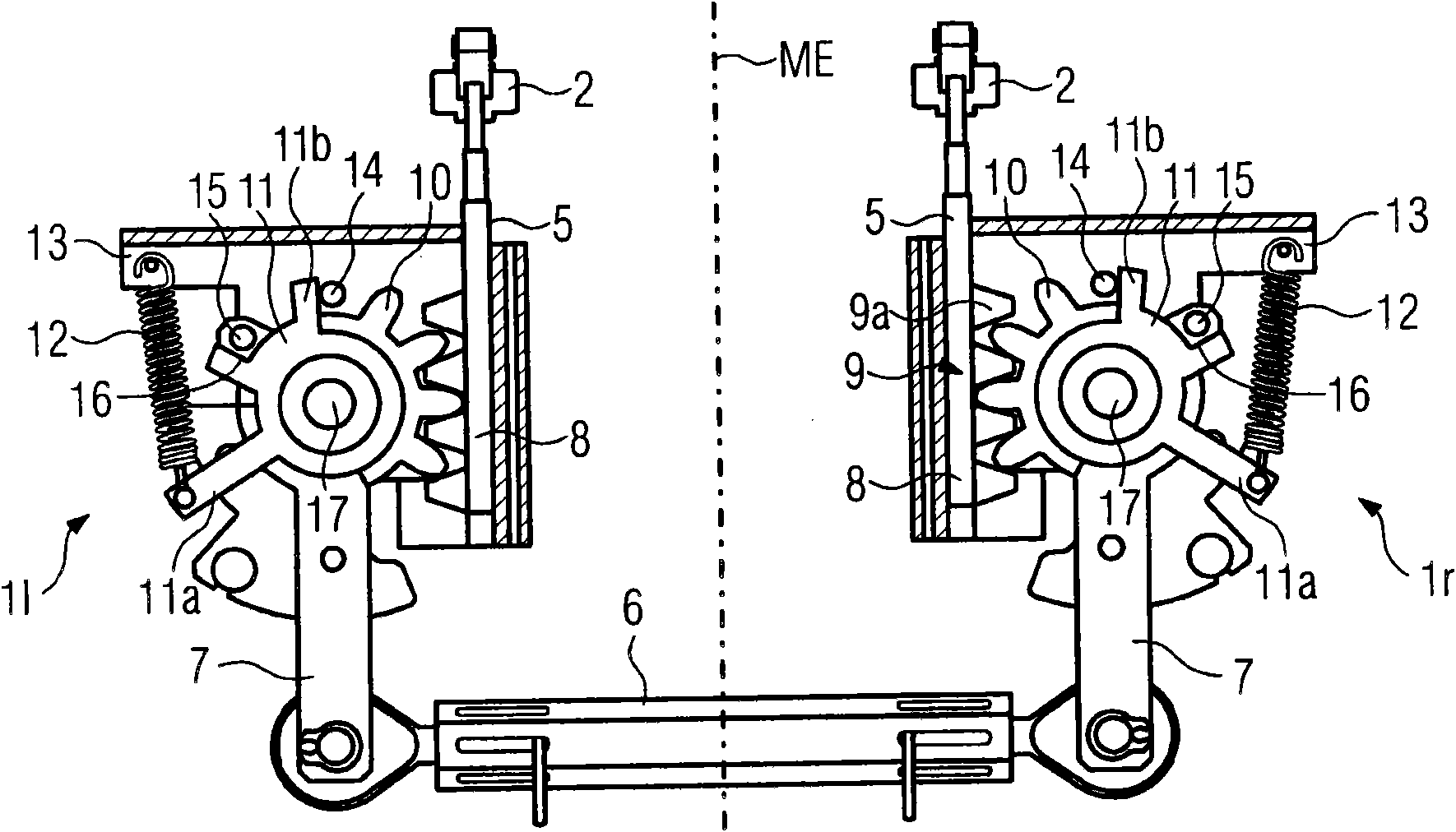
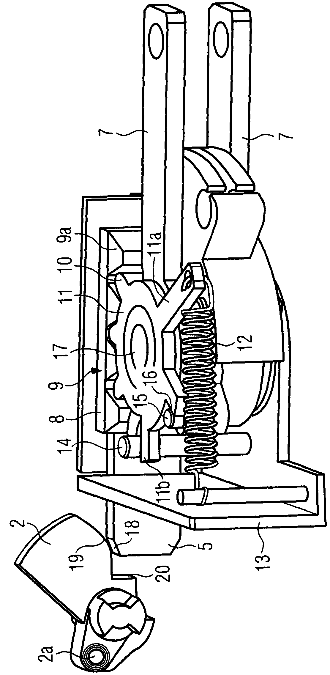
[0018] figure 1 A device 1 for interlocking two circuit breakers, hereinafter referred to as switches, is shown. For simplification reasons, in figure 1 Only the control plate 2 of the two switches is shown in simplified form, which can be pivoted about the axis 2a by a drive shaft of the switch, also not shown. Two switches are fastened adjacent to each other on corresponding mounting plates, that is to say on the rear of the switches, to which they are fastened by means of corresponding fastening plates (for example corner plates). figure 1 Through holes 4 for fixing screws are shown. Control sheet 2 (according to figure 1 Shown on the left) thus belongs to the left switch, and correspondingly the right control piece 2 belongs to the right switch. The device consists of two components, component 11 is the left switch and another component is assigned to the right switch. The two components 11 , 1r each have a frame 13 which here at the same time has the function of the ...


PUM


Abstract

A device for mutual locking of two switches has two tappets (5) which can move in the counter direction by a forced coupling connection, when the switch is on, one tappet is pushed to an opening position and the other one tappet is pushed to a locking position. In order to implementing free-maintenance , each tappet is provided with teeth bars (9) respectively with gears (10), radial levers (7) are respectively arranged on the gear and can overcome the deflecting of a pressure spring, the levers are connected by a joint lever (6), stop levers (11) are rotatingly arranged on each gear, the stop levers are respectively butted against on fixed stop parts (14), driven parts (15) are arranged fixedly and are respectively butted against on the stop surfaces of the stop levers, when one tappet is pushed to the opening position, the stop levers can be kept in the position, the other one tappet is pushed to the stop parts, and the driven parts can enable the stop levers to overcome the deflecting of a pulling force spring, wherein, the levers can overcome the other one deflecting of the pressure spring by the stop parts.

Description

technical field [0001] The invention relates to a device according to the preamble of claim 1 for interlocking two switches, in particular circuit breakers. Background technique [0002] Interlocking devices are known as accessories for circuit breaker arrangements with two switches arranged next to each other. The interface between the circuit breaker and the locking device is often designed here as a control disc-tappet mechanism, wherein the control disc can be integrated in the drive shaft inside the switch. The locking device is actuated via the control plate, so that the switching on of the respective switch is locked. In this case, the tappet protrudes into the circuit breaker and forms the connection between the inner control plate and the outer locking device. To lock the two switches with one another, two tappets are used, which are movable counter to each other in the longitudinal direction of the tappets by means of a mechanical positive coupling connection. W...

Claims


Application Information

Patent Timeline
Patent Type & Authority Applications(China)
IPC IPC(8): H01H9/26H01H71/00
CPCH01H9/26
Inventor 克劳斯·克鲁埃尔米歇尔·赫斯哈拉尔德·克里格
Owner SIEMENS AG
Why Eureka
Try Eureka