
Reconstruction and restoration of two polarization components of an optical signal field

a polarization component and optical signal technology, applied in the field of polarization component reconstruction of optical signal field, can solve the problems of pmd tolerance of only about 50%, limited capability of epmdc with a conventional direct-detection receiver, etc., and achieve the effect of saving cost and accurate measurement of intensity profil

Inactive Publication Date: 2010-10-26
ALCATEL-LUCENT USA INC
View PDF25 Cites 9 Cited by
  • Summary
  • Abstract
  • Description
  • Claims
  • Application Information

AI Technical Summary

Benefits of technology

"The invention is about a method for reconstructing the complex field of an optical signal, which includes both amplitude and phase information, at a receiver using a dual-polarization direct differential receiver. The method involves separating the received optical signal into two polarization components and processing them separately using digital signal processing to develop a digital representation of the polarizations. The two polarization components are then jointly processed to develop a \"generic\" polarization component that represents the received optical signal. The invention also includes a searching technique to determine the relative phase difference between the two reference points used in the two polarization components. The invention can be implemented using free space or fiber based optics and can be used with various types of optical differential phase-shift keying signals. The technical effects of the invention include improved signal quality, reduced cost, and more accurate signal measurement."

Problems solved by technology

However, the capability of the EPMDC with a conventional direct-detection receiver is quite limited in that the improvement in PMD tolerance is usually only about 50%.

Method used


Image

  • Reconstruction and restoration of two polarization components of an optical signal field
  • Reconstruction and restoration of two polarization components of an optical signal field
  • Reconstruction and restoration of two polarization components of an optical signal field

Examples


Embodiment Construction

[0030]The following merely illustrates the principles of the invention. It will thus be appreciated that those skilled in the art will be able to devise various arrangements that, although not explicitly described or shown herein, embody the principles of the invention and are included within its spirit and scope. Furthermore, all examples and conditional language recited herein are principally intended expressly to be only for pedagogical purposes to aid the reader in understanding the principles of the invention and the concepts contributed by the inventor(s) to furthering the art, and are to be construed as being without limitation to such specifically recited examples and conditions. Moreover, all statements herein reciting principles, aspects, and embodiments of the invention, as well as specific examples thereof, are intended to encompass both structural and functional equivalents thereof. Additionally, it is intended that such equivalents include both currently known equivale...


PUM


Abstract

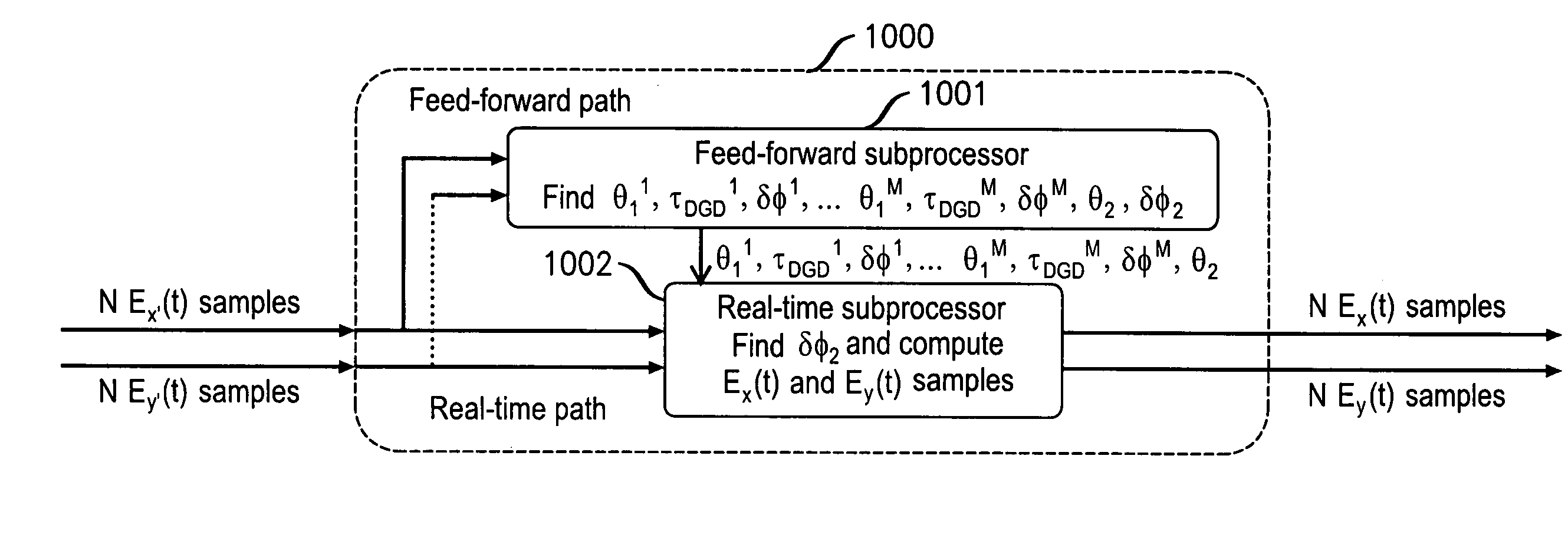
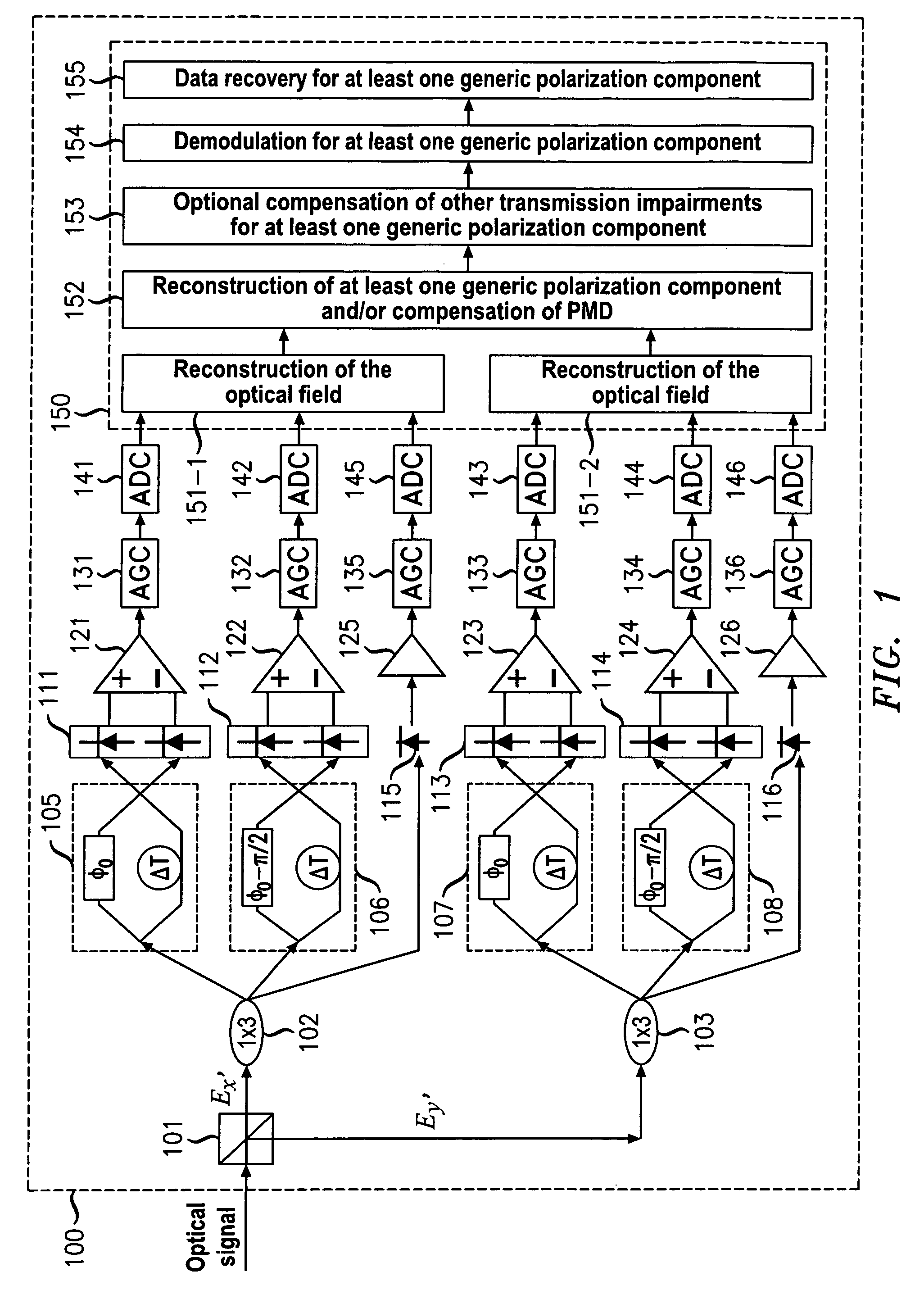
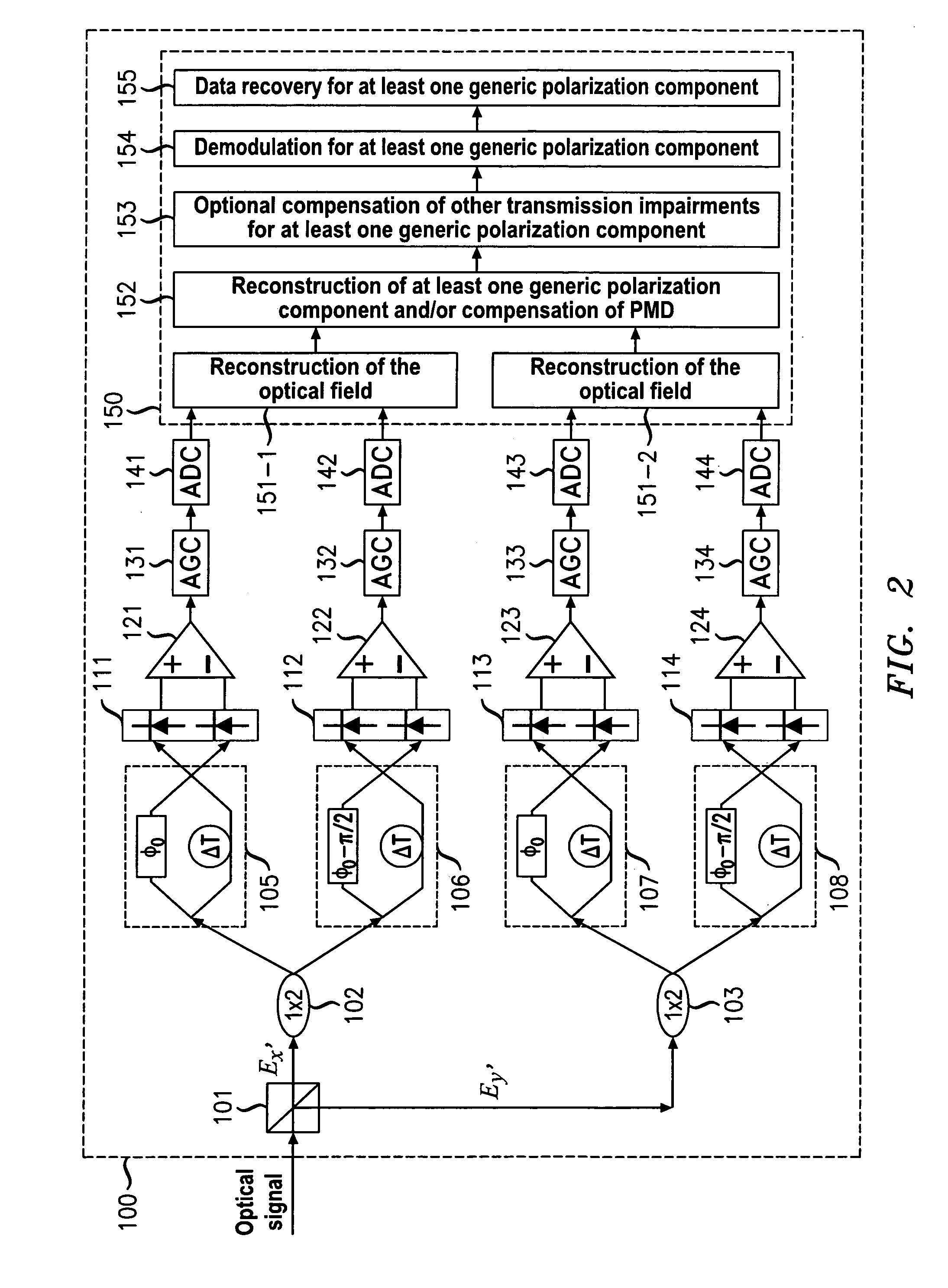
Digital compensation of the polarization-mode dispersion (PMD) effects experienced by an optical signal in a transmission link is achieved. A digital representation of the optical fields of two orthogonal polarization components of an optical signal, defined by a polarization beam splitter (PBS), is first obtained. The fiber transmission link is treated as a concatenation of multiple virtual PMD segments, each having two specific principle-state-of-polarization (PSP) axes and causing a differential group-delay (DGD) and a phase delay between two signal components that are polarized along the two PSP axes. The best guesses of the parameters of the PMD segments and the relative orientation between the PSP axes of the last PMD segment and the characteristic polarization axes of the PBS are dynamically obtained. The digital representation of at least one generic component of the field of the optical signal is then computed through matrix operations by using the best guesses.

Description

CROSS-REFERENCE TO RELATED APPLICATIONS[0001]This application is a divisional of U.S. patent application Ser. No. 12 / 002,006, filed Dec. 14, 2007, which claims benefit of U.S. provisional patent application Ser. No. 60 / 993,823, filed Sep. 14, 2007, each of which are herein incorporated by reference.TECHNICAL FIELD[0002]This invention relates to the reconstruction of the two polarization components of an optical signal field and compensation for polarization-mode dispersion.BACKGROUND OF THE INVENTION[0003]As is well known, an optical signal may have two orthogonal polarization states, each of which may have different properties. Sometimes such polarization states are intentionally introduced, such as in creating a polarization-multiplexed signal in which the two orthogonal polarization states of the optical carrier are arranged so that each carries different data in order to double the spectral efficiency. Such a polarization-multiplexed signal has two so-called “generic” polarizati...

Claims


Application Information

Patent Timeline
Patent Type & Authority Patents(United States)
IPC IPC(8): H04B10/00
CPCH04B10/2513H04B10/67H04B10/60H04B10/69H04B10/677
Inventor LIU, XIANG
Owner ALCATEL-LUCENT USA INC
Learn More