Clamping device

A clamping device and clamp locking technology, which is applied in the direction of workpiece clamping devices and manufacturing tools, can solve the problems of low efficiency and high labor intensity, and achieve fast and powerful clamping, free alignment, and reduced clamping labor intensity. Effect

Inactive Publication Date: 2012-03-14
九江七所精密机电科技有限公司
View PDF0 Cites 0 Cited by
  • Summary
  • Abstract
  • Description
  • Claims
  • Application Information

AI Technical Summary

Problems solved by technology

[0002] At present, the main methods of spline or flat key shaft-to-hole installation of hydraulic pumps are manual or various common clamping methods, such as hoisting, etc. The disadvantages are that the labor intensity is high and the efficiency is low.

Method used


Image

  • Clamping device
  • Clamping device
  • Clamping device

Examples


Embodiment

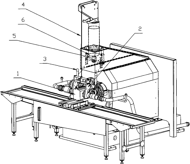
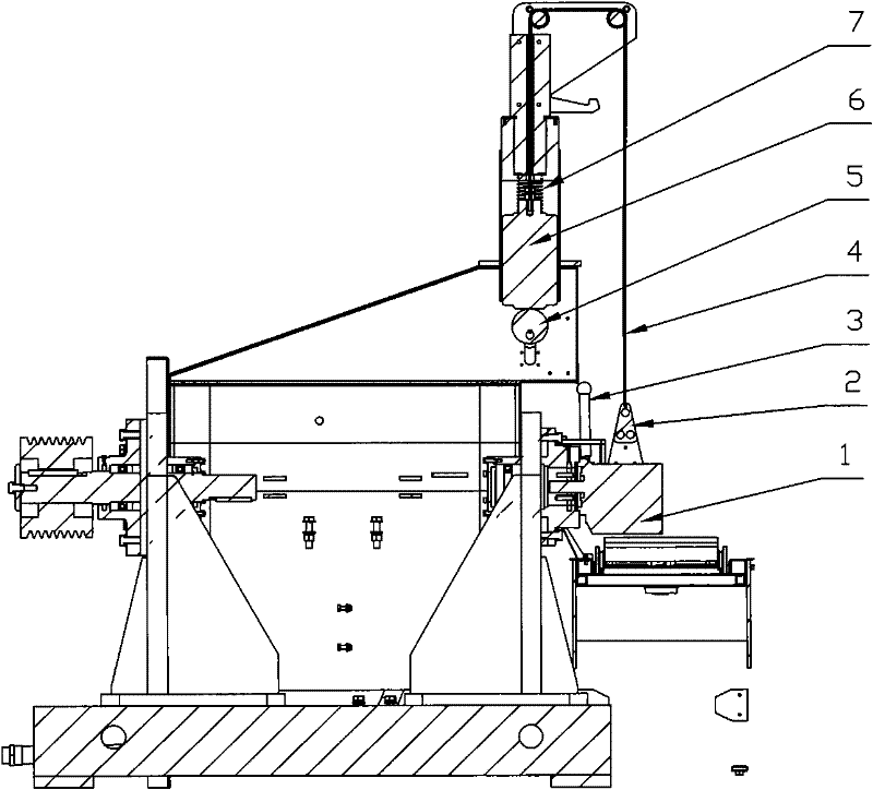
[0014] Install the alignment device and use the counterweight principle to hoist the hydraulic pump 1 through the steel wire rope 4. One end of the steel wire rope 4 is connected to the counterweight 6, and the other end is connected to the hydraulic pump 1 through the transition through the fixed pulley. The softness of the steel wire rope 4 is used. The six degrees of freedom of the hydraulic pump 1 are not restricted to achieve the purpose of convenient operation; the counterweight 6 is supported on the cam 5, and the stroke of the cam 5 is just equal to the initial position of the hydraulic pump 1 when it is placed on the station. The height difference from the location to the installation location. The cam 5 is coaxially connected with the operating handle 3, and the cam 5 is driven to rotate by rotating the handle 3, thereby lifting or lowering the counterweight 6 to realize switching of the counterweight and non-counterweight states of the hydraulic pump 1;

[0015] Its...


PUM


Abstract

The invention relates to a clamping device, which comprises a hoisting claw. A transposition locking clamp is arranged at the lower end of the hoisting claw; the hoisting claw is connected with a steel wire rope and is connected with a counterweight block through a pulley; and a cam is arranged at the lower end of the counterweight block, so that the hole aligning arrangement of a spline or a flat key shaft of a hydraulic pump is labor-saving and efficient, the clamping labor strength is reduced greatly, and the clamping device has the characteristics of labor saving and high efficiency.

Description

technical field [0001] The invention relates to a clamping device, in particular to a clamping device for installing a spline or a flat key shaft of a hydraulic pump to a hole. Background technique [0002] At present, the spline or flat key shaft-to-hole installation of hydraulic pumps mainly includes manual methods or various common clamping methods, such as hoisting, etc., which have the disadvantages of high labor intensity and low efficiency. Contents of the invention [0003] The object of the present invention is to provide a clamping device, which greatly reduces the labor intensity of clamping and has the characteristics of labor saving and high efficiency. [0004] The technical solution adopted to achieve the above purpose includes a hoisting claw. The lower end of the hoisting claw is provided with an indexing and locking fixture. The hoisting claw is connected to a steel wire rope and connected to a counterweight through a pulley. The lower end of the counterw...

Claims


Application Information

Patent Timeline
Patent Type & Authority Patents(China)
IPC IPC(8): B25B11/02
Inventor 王富安喻峰张永红陶桂金胡恺宋显国黄惠文
Owner 九江七所精密机电科技有限公司
Why Eureka
Try Eureka