Long beam part machining deformation control method

A technology for part processing and deformation control, applied in metal processing and other directions, can solve the problems of small buffering effect of side bending deformation, the amount of deformation cannot be ignored, the number of stress relief grooves, size constraints, etc., to ensure processing quality and reduce manual intervention. point, the effect of reducing the amount of side bending deformation

Active Publication Date: 2022-04-29
CHENGDU AIRCRAFT INDUSTRY GROUP
View PDF4 Cites 0 Cited by
  • Summary
  • Abstract
  • Description
  • Claims
  • Application Information

AI Technical Summary

Problems solved by technology

[0006] 1. There are many manual intervention points in the processing process, and the workers' clamping and processing experience are uneven, and the processing methods for the deformation of parts are different, resulting in the processing of the final parts from good to bad, which cannot be stabilized
[0007] 2. Due to the impact of the current international situation, a large number of imported materials have been replaced by domestic materials. From the analysis of processing performance alone, domestic materials cannot be compared with imported materials. The deformation of domestic materials is very common and the amount of deformation is large.
However, the original processing deformation control method is based on the deformation of imported materials, so it cannot completely solve the problem of processing deformation of domestic materials
[0008] 3. The processing equipment has been used for a long time, the precision and the stability of the spindle are no longer in the best state, and it is difficult to ensure stable milling during the processing
However, although the stress relief grooves are set, the method is relatively general, and there is no effective restriction on the number and size of the stress relief grooves, which greatly reduces the stress relief effect of the stress relief grooves
In addition, although the stress relief groove can reduce part of the deformation caused by stress release, for long beams, the deformation in the direction of the positioning surface cannot be ignored, and the anti-side bending holes cannot play any role in the deformation in the direction of the positioning surface. It can only play a small cushioning effect on the side bending deformation, so the deformation of the part still exists, and it cannot be eliminated twice

Method used


Image

  • Long beam part machining deformation control method
  • Long beam part machining deformation control method
  • Long beam part machining deformation control method

Examples


Embodiment 1

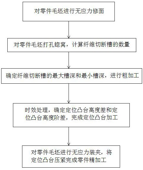
[0054] see Figure 1-Figure 5 , a processing deformation control method for long beam parts, comprising the following steps:

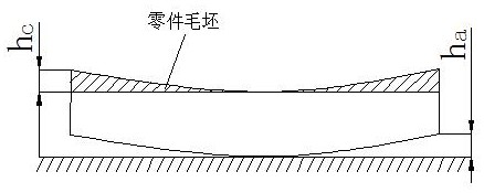
[0055] a. Place the part blank horizontally and observe the deformation of the part blank. The maximum deformation is h a , and then carry out stress-free shaving on the part blank, the amount of stress-free shaving is , so that h c ≥ h a ;

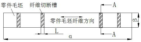
[0056] b. Punch and spot-face the blank of the part, according to the length of the blank of the part and part blank width Calculate the number n of the fiber cutting grooves, and arrange the fiber cutting grooves evenly;

[0057] c. According to the maximum groove depth allowance distribution of the part blank D 1 and the minimum groove depth margin distribution D 2 Determine the maximum groove depth h of the fiber cutting groove e and minimum groove depth h f , select a tool with a diameter of D for rough machining, and the width of the rough machining fiber cutting groove is L, so that D<L≤2D;

[...

Embodiment 2

[0062] see Figure 1-Figure 5 , a processing deformation control method for long beam parts, comprising the following steps:

[0063] a. Place the part blank horizontally and observe the deformation of the part blank. The maximum deformation is h a , and then carry out stress-free shaving on the part blank, the amount of stress-free shaving is , so that h c ≥ h a ;

[0064] b. Punch and spot-face the blank of the part, according to the length of the blank of the part and part blank width Calculate the number n of the fiber cutting grooves, and arrange the fiber cutting grooves evenly;

[0065] c. According to the maximum groove depth allowance distribution of the part blank D 1 and the minimum groove depth margin distribution D 2 Determine the maximum groove depth h of the fiber cutting groove e and minimum groove depth h f , select a tool with a diameter of D for rough machining, and the width of the rough machining fiber cutting groove is L, so that D<L≤2D;

[...

Embodiment 3

[0071] see Figure 1-Figure 5 , a processing deformation control method for long beam parts, comprising the following steps:

[0072] a. Place the part blank horizontally and observe the deformation of the part blank. The maximum deformation is h a , and then carry out stress-free shaving on the part blank, the amount of stress-free shaving is , so that h c ≥ h a ;

[0073] b. Punch and spot-face the blank of the part, according to the length of the blank of the part and part blank width Calculate the number n of the fiber cutting grooves, and arrange the fiber cutting grooves evenly;

[0074] c. According to the maximum groove depth allowance distribution of the part blank D 1 and the minimum groove depth margin distribution D 2 Determine the maximum groove depth h of the fiber cutting groove e and minimum groove depth h f , select a tool with a diameter of D for rough machining, and the width of the rough machining fiber cutting groove is L, so that D<L≤2D;

[...


PUM


Abstract

The invention discloses a long beam type part machining deformation control method, which belongs to the technical field of aviation structural part numerical control machining, and is characterized by comprising the following steps: a, carrying out stress-free surface trimming on a part blank; b, punching and dimpling the part blank, and calculating the number of fiber cutting grooves; c, the maximum groove depth and the minimum groove depth of the fiber cutting groove are determined, and rough machining is conducted; d, aging treatment is conducted, the positioning boss height difference and the positioning boss height step difference are determined, and positioning boss machining is completed; and e, unstressed clamping is conducted on the part blank, the positioning boss is pressed, and finish machining of the part is completed. By accurately calculating the number and the size of the fiber cutting grooves, the deformation of the part blank can be reduced to the greatest extent, the positioning surface and the lateral bending deformation can be reduced, an anti-lateral bending hole is not needed, the residual deformation eliminated by the fiber cutting grooves can be accurately eliminated by organically combining the fiber cutting grooves with the positioning boss, and the production efficiency is improved. And performing secondary elimination on the deformation.

Description

technical field [0001] The invention relates to the technical field of numerical control machining of aeronautical structural parts, in particular to a method for controlling machining deformation of long beam parts. Background technique [0002] Long beam parts refer to parts with an aspect ratio greater than 10. With the development of aerospace structural parts manufacturing technology, as aircraft structural parts are developing in the direction of integration, large-scale and theoretically complex shapes, the proportion of long beam parts is increasing, and the processing difficulty is also increasing. [0003] Long beam parts are easily deformed in the process of CNC machining. The most common situation is that the middle part of the part is arched, which makes the parts unable to be clamped normally and affects the CNC machining. Aiming at the problem of easy deformation of long beam parts, the current measure is to divide the processing process of parts into rough m...

Claims


Application Information

Patent Timeline
IPC IPC(8): B23P25/00
CPCB23P25/00
Inventor 方雨舟周进张也钟建张杨胡龙
Owner CHENGDU AIRCRAFT INDUSTRY GROUP
Why Eureka
Try Eureka