Bundling device

The technology of a strapping device and driving device, which is applied to the parts and packaging of strapping machines, can solve the problems of difficult statistics and control of the amount of strapping, unstable quality, and large investment in equipment, so as to realize large-scale continuous automatic production, The effect of good quality stability and small investment in equipment

Active Publication Date: 2010-11-17
王智国
View PDF4 Cites 10 Cited by
  • Summary
  • Abstract
  • Description
  • Claims
  • Application Information

AI Technical Summary

Problems solved by technology

[0002] At present, various flexible wires such as nonel tubes and flexible cables are mainly bundled manually after being wound into wire handles, which has the following disadvantages: (1) continuous automatic production cannot be realized, and the efficiency is low; (2) wire handles are wound into wire handles. 1. It may undergo mechanical disassembly, manual disassembly or natural drop before bundling, which is prone to loose handles, thus affecting the subsequent bundling quality; (3) The quality of manual bundling is greatly affected by the personal factors of the operator, and the quality is unstable; ( 4) The amount of strapping is not easy to count and control
[0003] In order to improve efficiency and reduce labor intensity, various strapping equipment have also appeared, which are generally special equipment in the industry. The structure is relatively complicated and the investment in equipment is relatively large.

Method used


Image

  • Bundling device
  • Bundling device
  • Bundling device

Examples


Embodiment Construction

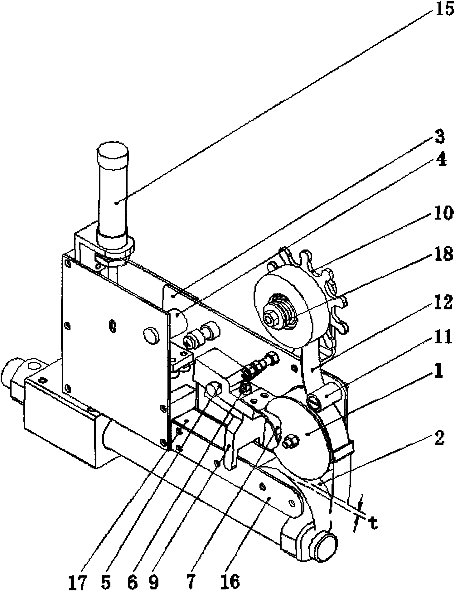
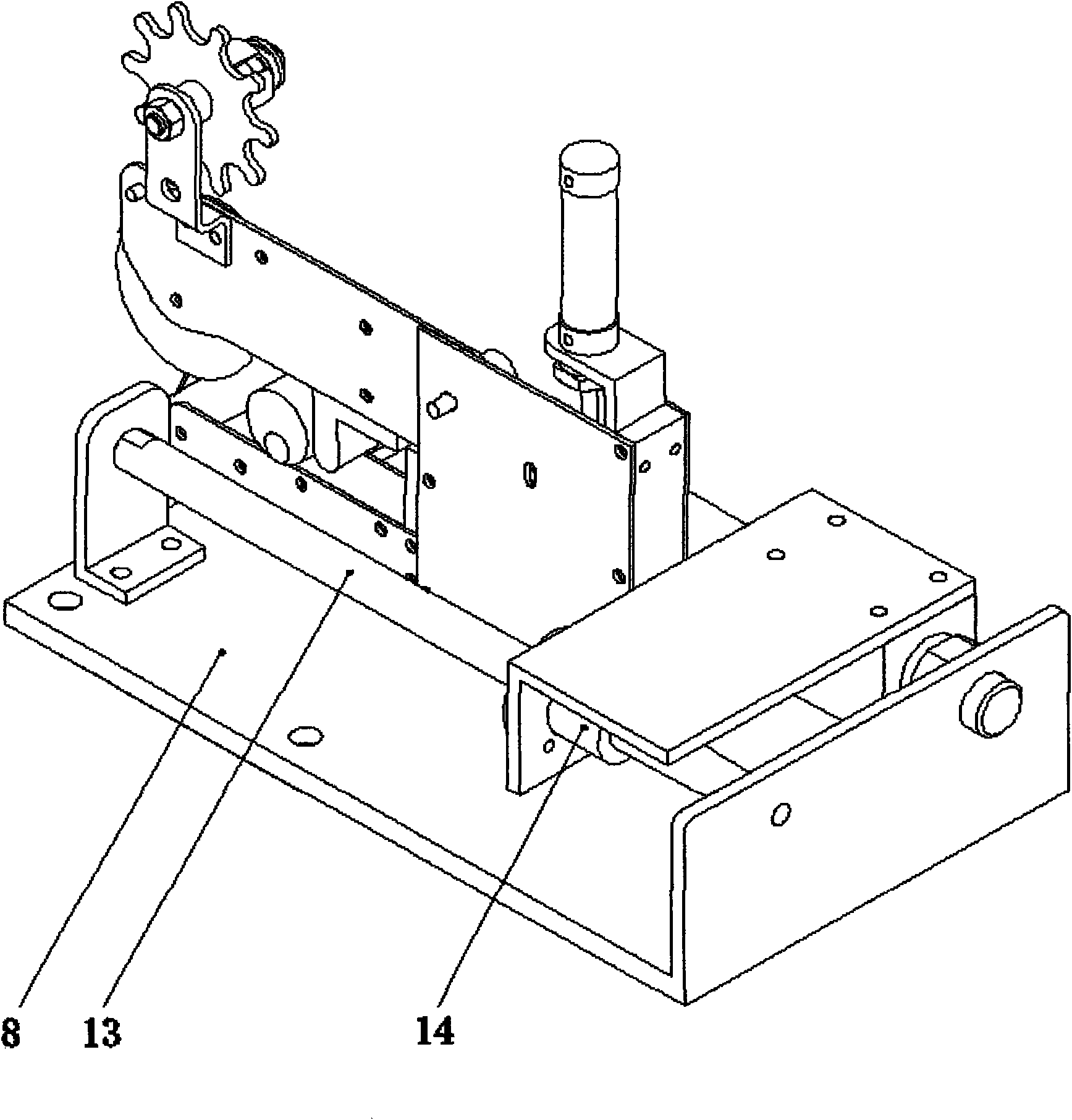
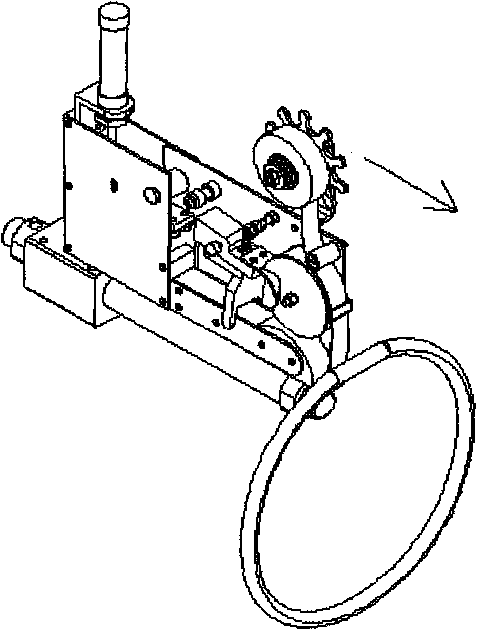
[0016] Such as figure 1 , 2 As shown, the present invention relates to a strapping device, which includes a headstock and an upper tape fixing part 1, a lower tape fixing part 2 and a tape installation shaft 18 installed on the headstock, and the upper and lower tapes are fixed The parts are distributed up and down alternately, and the gap between the two constitutes a tape wrapping channel, and the tape wrapping channel is used for the line to be bundled to carry the tape strip 12 through it.

[0017] The upper and lower adhesive tape fixing parts are preferably arc-shaped on their opposite surfaces, and the rear part of the adhesive tape wrapping channel formed by this is a flared opening with a large outside and a small inside. Thus, the surface of the upper and lower fixing parts can be smoothly contacted with the wire handle and gradually squeeze the adhesive tape so that it can be reliably bonded to the wire handle, avoiding that the surfaces of the upper and lower fix...


PUM


Abstract

The invention relates to a bundling device which comprises a frame, a headstock base, a movable side plate of a headstock, an upper adhesive tape fixture, an adhesive tape shearing device and a lower adhesive tape fixture, wherein, the headstock base is arranged on the frame and can move forwards and backwards; the movable side plate of the headstock is arranged on the headstock base and can swing; the upper adhesive tape fixture and the adhesive tape shearing device are arranged on the movable side plate of the headstock; and the lower adhesive tape fixture is arranged on the headstock base, and the upper position and the lower position of the lower adhesive tape fixture can be adjusted. The clearance between the upper adhesive tape fixture and the lower adhesive tape fixture forms an adhesive tape wrapping channel, and the shearing position of the adhesive tape shearing device is positioned in the front of the adhesive tape wrapping channel. The adhesive tape shearing device comprises a cutter bar, a separation blade and a cutter blade which are fixed on the cutter bar, the front of the cutter bar is hinged with the movable side plate of the headstock through a rotating shaft of the cutter bar, and the back of the cutter bar is equipped with a spring for lifting up the cutter bar. The bundling device can automatically complete the whole bundling process, and has the advantages of simple structure, low cost, reliable operation and the like; and the bundling device can be applied to bundling operation in various industries, thus greatly improving production efficiency.

Description

technical field [0001] The invention relates to a binding device, which can be used for automatic binding of nonel tubes and other similar flexible wires (hereinafter referred to as wires for short). Background technique [0002] At present, various flexible wires such as nonel tubes and flexible cables are mainly bundled manually after being wound into wire handles, which has the following disadvantages: (1) continuous automatic production cannot be realized, and the efficiency is low; (2) wire handles are wound into wire handles. 1. It may undergo mechanical disassembly, manual disassembly or natural drop before bundling, which is prone to loose handles, thus affecting the subsequent bundling quality; (3) The quality of manual bundling is greatly affected by the personal factors of the operator, and the quality is unstable; ( 4) The amount of strapping is not easy to count and control. [0003] In order to improve efficiency and reduce labor intensity, various strapping e...

Claims


Application Information

Patent Timeline
IPC IPC(8): B65B27/06B65B13/18B65B61/06
Inventor 王智国
Owner 王智国
Why Eureka
Try Eureka