Unlock instant, AI-driven research and patent intelligence for your innovation.
Measurement method and measurement accessory for zero point calibration of gear measuring center
What is Al technical title?
Al technical title is built by PatSnap Al team. It summarizes the technical point description of the patent document.
A technology for gear measurement and zero point calibration, which is used in the testing of machine gear/transmission mechanism, measuring devices, instruments, etc. Effect
Inactive Publication Date: 2010-11-17
XIAN TECHNOLOGICAL UNIV
View PDF6 Cites 32 Cited by
Summary
Abstract
Description
Claims
Application Information
AI Technical Summary
This helps you quickly interpret patents by identifying the three key elements:
Problems solved by technology
Method used
Benefits of technology
Problems solved by technology
[0010] The present invention provides a measurement method and accessories for gear measurement center zero point calibration to overcome the zero point of the gear measurement center caused by the measurement stroke in the prior art The problem of inconvenient calibration
Method used
Image
Click on the blue label to locate the original text in one second.
Reading with bidirectional positioning of images and text.
Examples
Embodiment 1
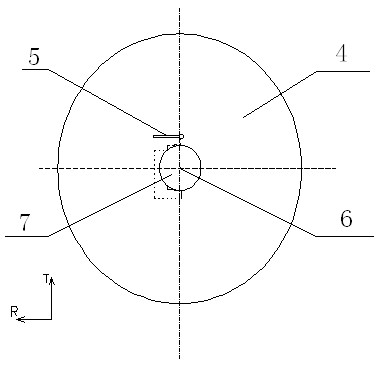
[0050] see Figure 7 The force is measured in the horizontal direction (T direction). The specific steps are:
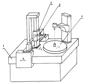
[0051] 1. Place the standard ball 8 at a suitable position in the upper space of the rotary shaft table 4 of the gear measurement center through the attachment, so as to ensure that the measuring head 5 can touch the standard ball 8 within the stroke range;
[0052] 2. According to the force measuring direction of the probe 5, manually move the probe 5 so that it is directly in front of the force measuring direction of the standard ball 8 (such as image 3 );
[0053] 3. Driven by the gear measurement center, drive the measuring head 5 to contact the standard ball 8, and measure six uniform points within the semicircle range of the horizontal section in contact with the standard ball 8 and the measuring head 5, and according to the least square circle The coordinate values of each axis of the center of the sphere (T1, R1, q1) are calculated by the method; the au...
Embodiment 2
[0059] For the gear measurement center using a three-dimensional measuring head, the method of Embodiment 1 can be used for zero point calibration.
Embodiment 3
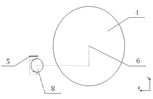
[0061] see Figure 8 , Measuring force of the probe 5 is in the vertical direction (Z direction). The specific implementation steps are as follows:
[0062] 1. After the gear measurement center is powered on, the indication values of the gratings on each axis will be cleared. Adsorb the standard ball 8 on the rotary table 4, manually move the measuring head 5 to the position 1 directly above the standard ball 8 (such as Figure 4 );
[0063] 2. Driven by the gear measurement center, the measuring head 5 is automatically driven to move along the R and Z directions, contact with the standard ball 8, and measure the uniformity within a quarter circle of the vertical section of the standard ball 8 and the measuring head 5. Six points, and calculate the R-axis coordinate value R1 of the center of the sphere based on the six points (such as Figure 5 );
[0064] 3. The measuring head 5 returns to the starting point, automatically drives the measuring head 5 to move along the ...
PUM
Abstract
The invention relates to a measurement method and a measurement assessor for the zero point calibration of a gear measurement center. In the prior art, the problem of incapability of meeting measuring requirements of large and small-size workpieces simultaneously due to inconvenient zero point calibration of the gear measuring center caused by a measuring stroke exists. The invention provides the measurement method and the measurement accessory of the zero point calibration of the gear measuring center. The method comprises the following steps of: arranging a standard sphere at the measuring position where any measuring heads can contact on the upper part of a rotary shaft table to obtain absolute coordinates (T1, R1 and q1) of the centre of sphere first; driving the rotary shaft table by a rotary shaft to rotate to allow the standard sphere to rotate to the other angle to obtain the other absolute coordinates (T2, R2 and q2) of the centre of sphere; and calculating the positions (T0 and R0) of a rotary center. The method provided by the invention has the advantages of simplicity, convenience and wide application range; and the accessory provided by the invention has the advantages of simple structure, reduction of the requirements on operators and low use cost.
Description
technical field [0001] The invention relates to the technical field of four-coordinate measuring machines, in particular to a measurement method for zero point calibration of a gear measurement center and an accessory for measurement. Background technique [0002] The gear measuring center is the crystallization of the integrated application of information technology, computer technology and numerical control technology on gear measuring instruments, and it is a milestone in the development of coordinate gear measuring instruments. It is mainly used for the detection of single geometric accuracy of gears, and can also be used for the measurement of the overall error of gears. It has the characteristics of wide measurement range, high precision and high efficiency. [0003] The gear measurement center is essentially a four-coordinate measuring machine with a rotation angle coordinate - a cylindrical coordinate measuring machine. When in use, the workpiece is installed betwe...
Claims
Application Information
Patent Timeline
Application Date:The date an application was filed.
Publication Date:The date a patent or application was officially published.
First Publication Date:The earliest publication date of a patent with the same application number.
Issue Date:Publication date of the patent grant document.
PCT Entry Date:The Entry date of PCT National Phase.
Estimated Expiry Date:The statutory expiry date of a patent right according to the Patent Law, and it is the longest term of protection that the patent right can achieve without the termination of the patent right due to other reasons(Term extension factor has been taken into account ).
Invalid Date:Actual expiry date is based on effective date or publication date of legal transaction data of invalid patent.

