Focus detection apparatus and control method thereof
A technology of focus detection and equipment, which is applied in the direction of focusing devices, instruments, installations, etc., can solve the problems of detection accuracy decline, achieve the effects of reducing capacity, high-precision focus detection, and improving focus detection accuracy
- Summary
- Abstract
- Description
- Claims
- Application Information
AI Technical Summary
Problems solved by technology
Method used
Image
Examples
no. 1 example
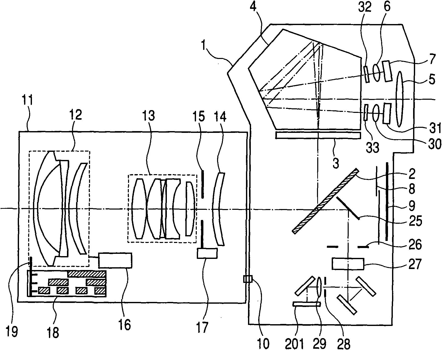
[0052] figure 1 is a block diagram showing an autofocus camera system including a single-lens reflex camera and an interchangeable lens to be mounted on the camera according to an exemplary embodiment of the present invention. The figure mainly shows the optical positional relationship of the system.
[0053] In this figure, a photographing lens 11 is mounted on the front of the camera body 1 . Optical components, mechanical components, electric circuits, and an imaging element such as a film or a CCD are housed in the camera body 1 , enabling pictures or images to be captured. The optical member 2 (hereinafter, referred to as an optical member) as a main mirror is obliquely disposed in the photographing optical path in the viewfinder observation state, and is withdrawn from the photographing optical path in the photographing state. In addition, the optical member 2 is configured as a half mirror that partially transmits or reflects incident light, and when the optical memb...
no. 2 example
[0102] In the first embodiment, compensation is performed by selecting any one of a plurality of pre-stored shading coefficients according to the light source judgment result.
[0103] The second embodiment described below is a typical embodiment that performs a compensation operation different from that of the first embodiment.
[0104] Figure 11 is a flowchart for explaining the automatic focus operation of the camera related to the second embodiment of the present invention. will refer to the aforementioned Figure 14 to illustrate Figure 11 The control flow shown.
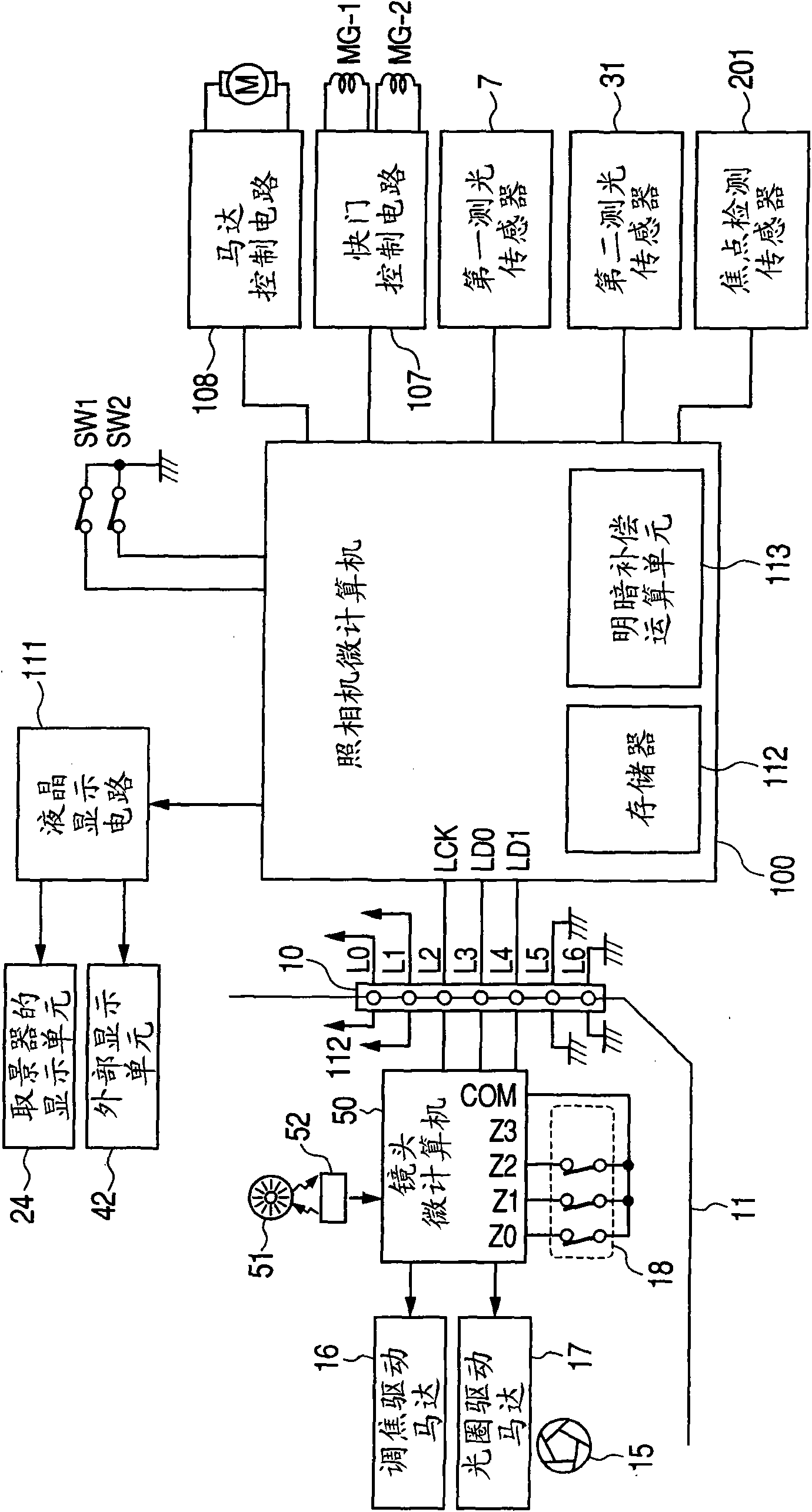
[0105] when pressed figure 2 When the switch SW1 on the camera body 1 is shown, the operation starts in step S401. In this case, the camera microcomputer 100 performs an accumulation operation of the line sensors 211 a , 211 b , 212 a , and 212 b in the focus detection sensor 201 . After accumulation starts, the accumulation status is monitored based on a signal from the focus detection sensor 201 . On...
no. 3 example
[0120] The cameras according to the first and second embodiments perform compensation based on light source detection results and a plurality of shading coefficients stored in advance.
[0121] The third embodiment described below is a typical embodiment that performs compensation operations different from those of the first and second embodiments.
[0122] Figure 12 is a flowchart for explaining the automatic focus operation of the camera related to the third embodiment of the present invention. will refer to the aforementioned Figure 14 to illustrate Figure 12 The control flow shown.
[0123] when pressed figure 2 When the switch SW1 on the camera body 1 is shown, the operation starts in step S501. In this case, the camera microcomputer 100 performs an accumulation operation of the line sensors 211 a , 211 b , 212 a , and 212 b in the focus detection sensor 201 . After accumulation starts, the accumulation status is monitored based on a signal from the focus detecti...
PUM
 Abstract
Description
Claims
Application Information
 - R&D
- Intellectual Property
- Life Sciences
- Materials
- Tech Scout
- Unparalleled Data Quality
- Higher Quality Content
- 60% Fewer Hallucinations
Browse by: Latest US Patents, China's latest patents, Technical Efficacy Thesaurus, Application Domain, Technology Topic, Popular Technical Reports.
© 2025 PatSnap. All rights reserved.Legal|Privacy policy|Modern Slavery Act Transparency Statement|Sitemap|About US| Contact US: help@patsnap.com


