Light-emitting element, illumination device, and liquid crystal display device

A technology for light-emitting elements and lighting devices, which is applied to lighting devices, optical elements, lighting and heating equipment, etc., can solve the problems of inability to obtain the uniformity of brightness of lighting devices, high cost, and obstacles to thinning of displays.

Inactive Publication Date: 2010-11-17
SHARP KK
View PDF3 Cites 17 Cited by
  • Summary
  • Abstract
  • Description
  • Claims
  • Application Information

AI Technical Summary

Problems solved by technology

However, the thickness of the current direct lighting device is about 20 mm to 40 mm, which hinders the further thinning of the display
[0006] In order to achieve further thinning of large liquid crystal displays, it can be solved by making the distance between the light source and the liquid crystal display panel close, but in this case, if the number of light sources is not increased, the brightness uniformity of the lighting device cannot be obtained
On the other hand, if the number of light sources is increased, the cost will increase

Method used


Image

  • Light-emitting element, illumination device, and liquid crystal display device
  • Light-emitting element, illumination device, and liquid crystal display device
  • Light-emitting element, illumination device, and liquid crystal display device

Examples


Embodiment approach 1

[0110] [Embodiment 1: When the holding part is provided on the light emitting surface of the light guide]

[0111]

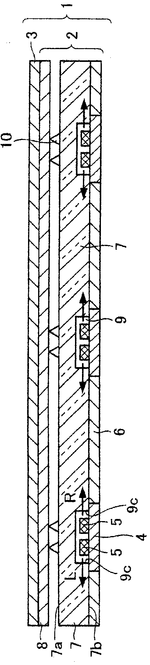
[0112] figure 2 It is a cross-sectional view showing a schematic configuration of a liquid crystal display device 1 according to an embodiment of the present invention. The liquid crystal display device 1 includes a backlight 2 (illumination device), and a liquid crystal display panel 3 arranged to face the backlight 2 .

[0113] The backlight 2 is disposed behind the liquid crystal display panel 3 (on the side opposite to the display surface). Such as figure 2 As shown, the backlight 2 includes a substrate 4, a light source 5, a reflective sheet 6, a light guide 7, an optical sheet 8, and a holding portion 10 (first protrusion or second protrusion).

[0114] The liquid crystal display panel 3 is the same as a general liquid crystal display panel used in a conventional liquid crystal display device, and although not shown, includes, for example, an active...

Embodiment approach 2

[0200] based on the following Figure 18-20 Other embodiments of the present invention will be described. In addition, for convenience of explanation, components having the same structure and function as those shown in the drawings of Embodiment 1 above are denoted by the same reference numerals, and description thereof will be omitted.

[0201] Such as Figure 18 As shown, the liquid crystal display device 1 of the present embodiment differs from the first embodiment described above in terms of the arrangement of the holding portion 10 . In this embodiment, the holding part 10 is not provided on the light emitting surface 7a of the light guide 7 (refer to figure 2 ), but on the side of the optical sheet 8. Such as Figure 18 As shown, as an example of the form of providing the holding portion 10 on the optical sheet 8 side, the holding portion 10 may be formed integrally with the transparent plate 13 or integrally formed with the diffuser plate constituting the optical s...

Embodiment approach 3

[0210] based on the following Figure 21-22 Another embodiment of the present invention will be described. In addition, for convenience of explanation, components having the same structure and function as those shown in the drawings of Embodiment 1 above are denoted by the same reference numerals, and description thereof will be omitted.

[0211] Such as Figure 21 As shown, the liquid crystal display device 1 of this embodiment differs from the above-mentioned Embodiments 1 and 2 in the point of installation of the holding portion 10 . In this embodiment, the holding part 10 is not provided on the light emitting surface 7a of the light guide 7 (refer to figure 2 ), but integrally formed with the transparent plate 13, and the transparent plate 13 is fixed on the lower surface 8a of the optical sheet 8 opposite to the light-emitting surface 7a by an adhesive.

[0212] As a result, the holding portion 10 does not protrude upward from the light emitting surface 7 a toward the...


PUM

PropertyMeasurementUnit
thicknessaaaaaaaaaa

Abstract

A light-emitting element (11) comprises a light source (5a), a light guide body (7) having a light-emitting surface (7a), and a holding portion (10). The light source (5a) has a directivity in which the component of light in a first direction parallel to the light-emitting surface (7a) becomes larger than the component of light in a direction perpendicular to the light-emitting surface (7a). The light guide body (7) has a light-receiving surface for receiving the component of light in the first direction. When the level of brightness on the light-emitting surface (7a) is divided into a plurality of steps from lower brightness to higher brightness, a position where the holding portion (10) is provided on the light-emitting surface (7a) is set to a first region where the brightness shows the lowest level. This provides a light-emitting element and an illumination device capable of improving the uniformity of brightness on a light-emitting surface.

Description

technical field [0001] The present invention relates to: a light-emitting element that converts a point-shaped light source or a linear light source into a planar light source by guiding the light emitted from a point-shaped light source or a linear light source to a light-emitting surface; a backlight for a liquid crystal display device equipped with the light-emitting element etc.; and a liquid crystal display device provided with the lighting device. Background technique [0002] In recent years, instead of cathode ray tubes (CRTs), liquid crystal display devices have been widely used in liquid crystal televisions, monitors, and mobile phones due to their features of energy saving, thinness, and light weight. As a method for further utilizing these advantages, improvement of an illuminating device (so-called backlight) disposed behind a liquid crystal display device may be mentioned. [0003] Lighting devices are roughly classified into side light type and direct light t...

Claims


Application Information

Patent Timeline
Patent Type & Authority Applications(China)
IPC IPC(8): F21S2/00G02F1/13357F21Y101/02
CPCG02F1/133611G02B6/0068G02F1/1336G02F1/133606G02B6/0035G02B6/0021
Inventor 神德千幸增田岳志味地悠作
Owner SHARP KK
Why Eureka
Try Eureka