Split rotating shaft joint

A rotating shaft, split-type technology, applied in the direction of load hanging components, earthmoving machines/shovels, construction, etc., can solve the problems of difficult to ensure coaxiality, difficult processing, difficult detection, etc., to achieve measurement and operation. Strong performance, simple processing technology, good dimensional accuracy

Inactive Publication Date: 2010-11-24
LONKING (SHANGHAI) HYDRAULIC CO LTD
View PDF8 Cites 4 Cited by
  • Summary
  • Abstract
  • Description
  • Claims
  • Application Information

AI Technical Summary

Problems solved by technology

Since the commonly used rotary shaft joint is an integral structure, the main shaft and the main body are usually relatively long, which is difficult to process and difficult to ensure coaxiality
The sealing groove and water distribution groove on the main body are relatively deep, so it is not easy to detect after processing, and coupled with the limitation of processing technology, the overall assembly effect is not good

Method used


Image

  • Split rotating shaft joint
  • Split rotating shaft joint
  • Split rotating shaft joint

Examples


Embodiment

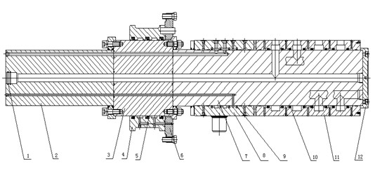
[0019] Such as figure 1 As shown, a split rotary shaft joint provided by the present invention includes split front shaft 2, central shaft 3, rear shaft 7, middle sleeve 4, oil distribution sleeve 8 and water distribution sleeve 11. After assembly, the central shaft 3 Located between the front axle 2 and the rear axle 7, a rear cover 12 is provided on the rear end of the rear axle 7, a middle sleeve 4 is placed on the center axle 3, and an oil distribution sleeve 8 and a water distribution sleeve 11 are placed on the rear axle 7 , guide rings are respectively embedded on the inner walls of the oil distribution sleeve 8 and the water distribution sleeve 11. There is a large flange 6 over the central shaft 3, and the large flange 6 is located at the side of the middle sleeve 4, and the seal between the large flange 6 and the middle sleeve 4 is sealed by an O-ring.

[0020] The middle shaft 3 and the middle sleeve 4 are sealed by soil and sand 5, the oil distribution sleeve 8 an...


PUM


Abstract

The invention relates to a split rotating shaft joint, which is characterized by comprising a front shaft, a middle shaft, a rear shaft, a middle sleeve, an oil distribution sleeve and a water distribution sleeve which are split, wherein after assembly, the middle shaft is positioned between the front shaft and the rear shaft; the middle sleeve is sleeved outside the middle shaft; and the oil distribution sleeve and the water distribution sleeve are sleeved outside the rear shaft. The split rotating shaft joint has the advantages of simplified processing technology, high measurement operability, good size precision, and better coaxiality after the assembly compared with an integral structure by adopting a split structure.

Description

technical field [0001] The invention relates to a rotary shaft joint, which is used in the field of construction machinery to deliver the hydraulic oil and electrical system of the vehicle to the executive mechanism of the vehicle. Background technique [0002] The rotary shaft joint is used in construction machinery such as cranes and excavators. It is a device that transmits the hydraulic oil and electrical system of the vehicle to the actuator of the vehicle. The commonly used rotary shaft joint is an integral structure, which consists of two parts: the main shaft and the main body. The main body in turn consists of the rotor, stator and seals. The rotor is fixed on the slewing platform and rotates with the slewing platform. The stator is fixed on the chassis. There is an oil circuit between the rotor and the stator through an annular oil tank. The angle between the rotor and the stator oil port is changed by the rotation of the rotor. Thereby changing the output port o...

Claims


Application Information

Patent Timeline
Patent Type & Authority Applications(China)
IPC IPC(8): B66C13/12E02F9/22
Inventor 林张荣黄延涛向兵徐君于杰
Owner LONKING (SHANGHAI) HYDRAULIC CO LTD
Why Eureka
Try Eureka