Percussive drilling construction process for diaphragm wall passing through rock-filled layer in reclamation area

An underground diaphragm wall and construction technology technology, applied in artificial islands, water conservancy projects, underwater structures, etc., can solve problems such as low construction work efficiency, and achieve the effects of reducing comprehensive construction costs, good quality of grooves, and high work efficiency

Inactive Publication Date: 2010-11-24
THE FIFTH ENG CO LTD OF CHINA TIESIJU CIVIL ENG GRP
View PDF3 Cites 16 Cited by
  • Summary
  • Abstract
  • Description
  • Claims
  • Application Information

AI Technical Summary

Problems solved by technology

[0003] The purpose of the present invention is to provide a construction technology of percussion drilling through the underground diaphragm wall of the rock filling layer in the sea reclamation area, which solves the problem of low construction efficiency of the underground diaphragm wall under the geological conditions of the rock filling layer, and has the advantages of high work efficiency an

Method used


Image

  • Percussive drilling construction process for diaphragm wall passing through rock-filled layer in reclamation area
  • Percussive drilling construction process for diaphragm wall passing through rock-filled layer in reclamation area

Examples


Embodiment

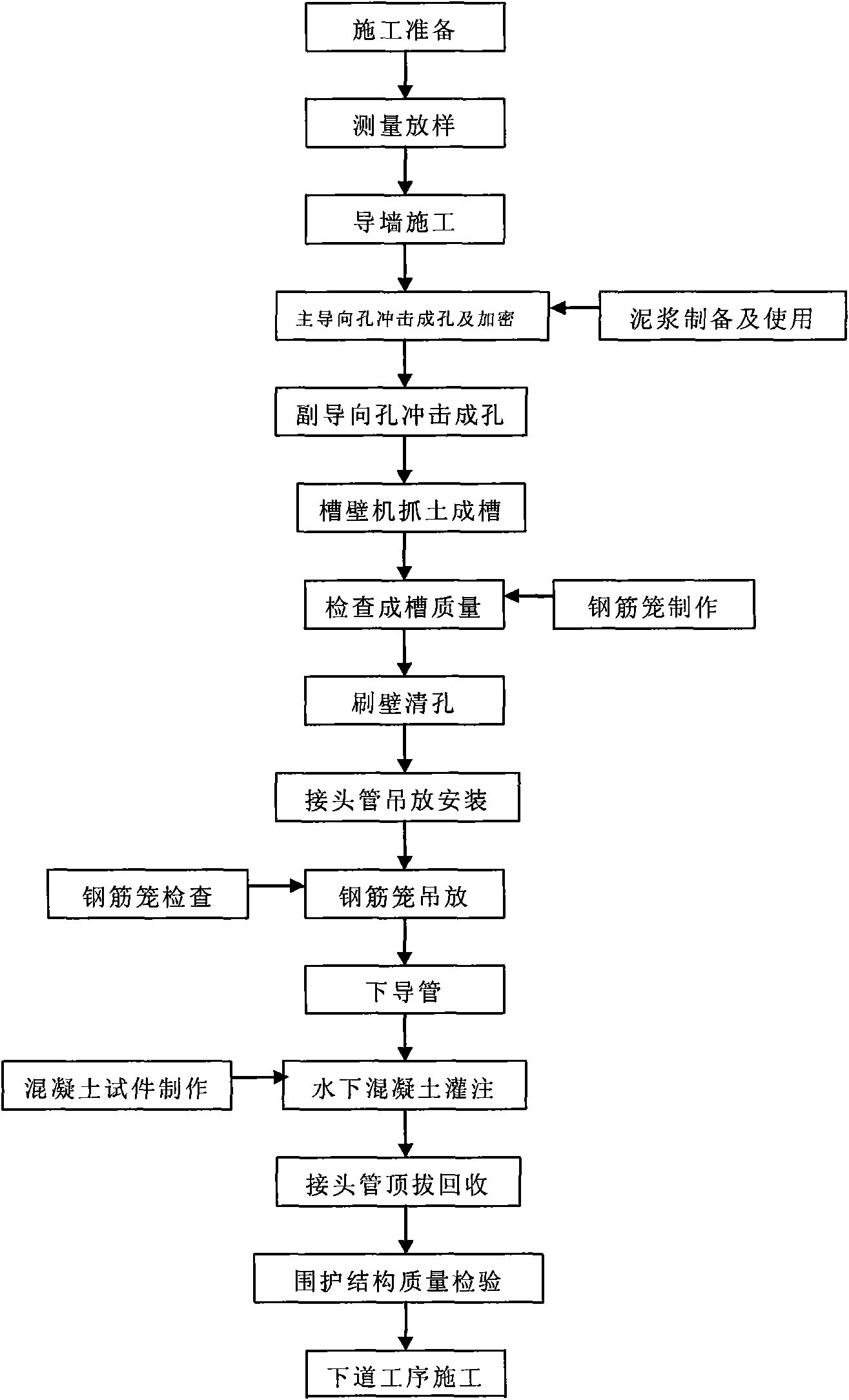
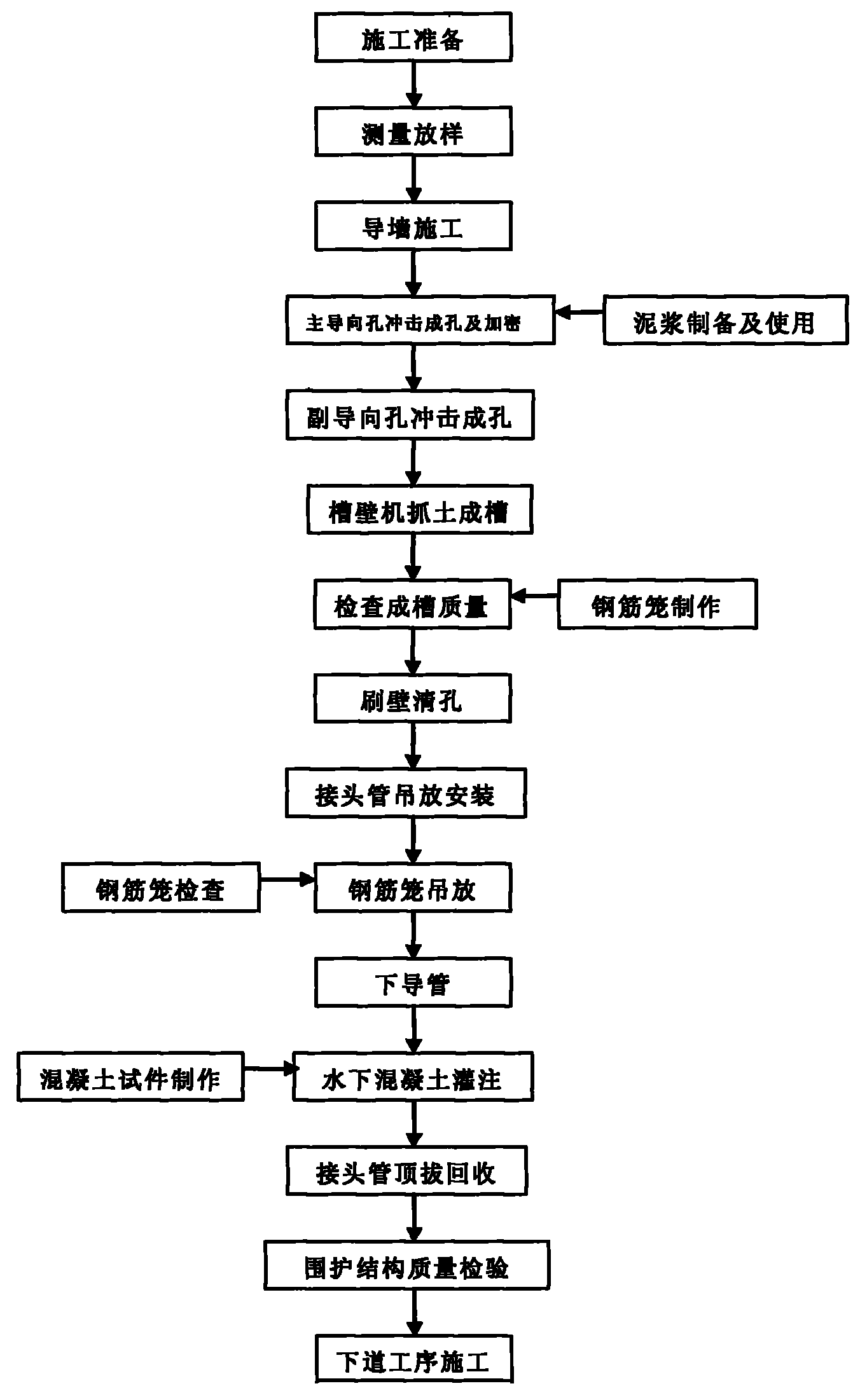
[0035] Measure and set out, accurately measure and set the position of the guide wall, and carry out the construction of the guide wall. After the guide wall is accepted, use the instrument to determine the framing line of the underground continuous wall. After the punching pile machine and the slotting machine are in place, first check whether the grab is parallel to the guide wall, and check the punching of the CZ-30 impact pile machine. Whether the center line of the hammer and the grab of the GB24 full hydraulic groove wall machine coincides with the center axis of the guide wall.

[0036] After the slot section is positioned, the positions of the main guide hole and the auxiliary guide hole are determined according to the length of each unit slot section. After the position of the guide hole is determined, first use the impact pile driver to continuously impact the main guide hole where the joint pipe is placed from the top surface of the diaphragm wall to a depth of 0.5m...


PUM


Abstract

The invention relates to a percussive drilling construction process for a diaphragm wall passing through a rock-filled layer in a reclamation area. The process comprises the following steps of: performing setting-out survey and lead wall construction; after the positions of guide holes are determined, first continuously punching main guide holes accommodating pipe joints, from the top side of the diaphragm wall to a depth which is 0.5m greater than a designed depth by using a punch pile machine, and then forming an encrypted main guide hole at the position which is between the two main guide holes and is 1.5m away from each of the main guide holes; after the position of the encrypted main guide hole is determined, performing continuous punching from the top side of the diaphragm wall by using a punch hammer, moving the punch pile machine to a position above the gap between the two main guide holes, then punching the gap between the two main guide holes by using the punching hammer so as to form an accessory hole, and digging soil by using a grooving machine to form a groove; brushing the wall and cleaning the holes; hoisting and installing the pipe joints; hoisting a steel reinforcement cage; lowering down conduits; filling underwater concrete; pulling and reclaiming the pipe joints; and checking the quality of an enclosure structure. Thus, the construction process solves the problem of low work efficiency during the construction of the diaphragm wall under the geological condition of the rock-filled layer, has the characteristics of high work efficiency and good grooving quality, improves the safety of foundation pit construction, and effectively reduces the comprehensive construction cost.

Description

technical field [0001] The invention relates to a construction technique of percussive drilling through an underground continuous wall of a rock filling layer in a sea reclamation area. technical background [0002] With the development of science and technology, in recent years, the construction technology of underground diaphragm wall has been fully developed and applied in soft soil strata such as cohesive soil, sandy soil and flush fill soil in my country. Especially in the near future, with the rapid development of the national economy, the development of underground space in coastal areas has also developed in depth. The construction methods of underground diaphragm wall enclosure structures used in the development of underground space are various. The traditional construction method uses groove walls for soft soil layers The machine directly drills and grasps the trough, and the upper hard and lower soft strata adopt the intensive impact method to form the trough. In...

Claims


Application Information

Patent Timeline
IPC IPC(8): E02D29/02
Inventor 付国才汪中汉孙成山鲍俊捷
Owner THE FIFTH ENG CO LTD OF CHINA TIESIJU CIVIL ENG GRP
Why Eureka
Try Eureka