Solenoid valve for active closing of solenoid injectors

A fuel injector, electromagnetic technology, applied to fuel injection devices, valve details, valve devices, etc., can solve problems such as no overpressure limit

Active Publication Date: 2016-09-14
ROBERT BOSCH GMBH
View PDF6 Cites 0 Cited by
  • Summary
  • Abstract
  • Description
  • Claims
  • Application Information

AI Technical Summary

Problems solved by technology

However, the pressure equalization solenoid valve usually does not have the function of overpressure limitation

Method used


Image

  • Solenoid valve for active closing of solenoid injectors
  • Solenoid valve for active closing of solenoid injectors
  • Solenoid valve for active closing of solenoid injectors

Examples


Embodiment Construction

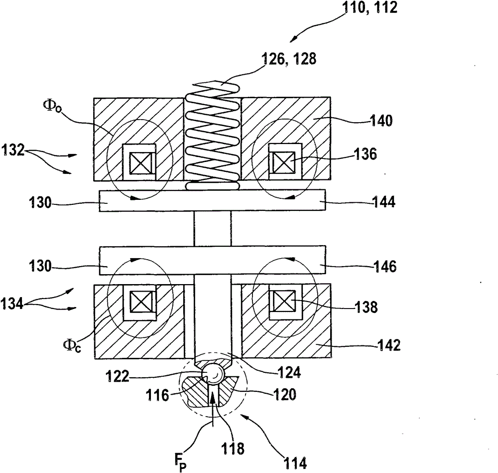
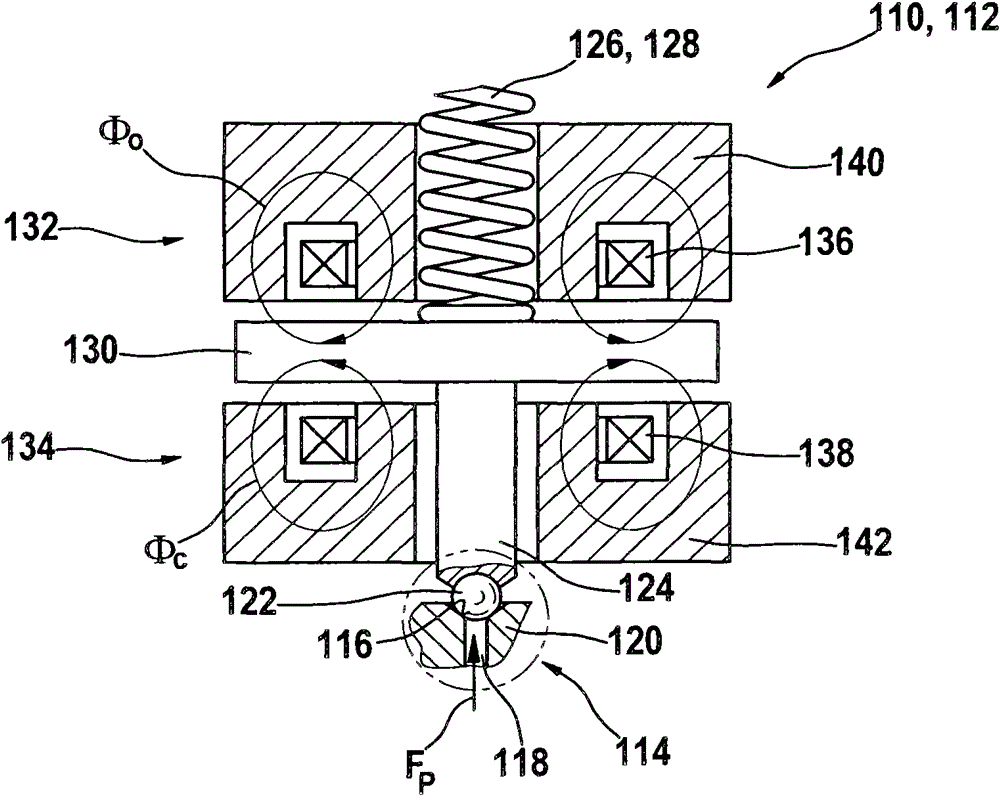
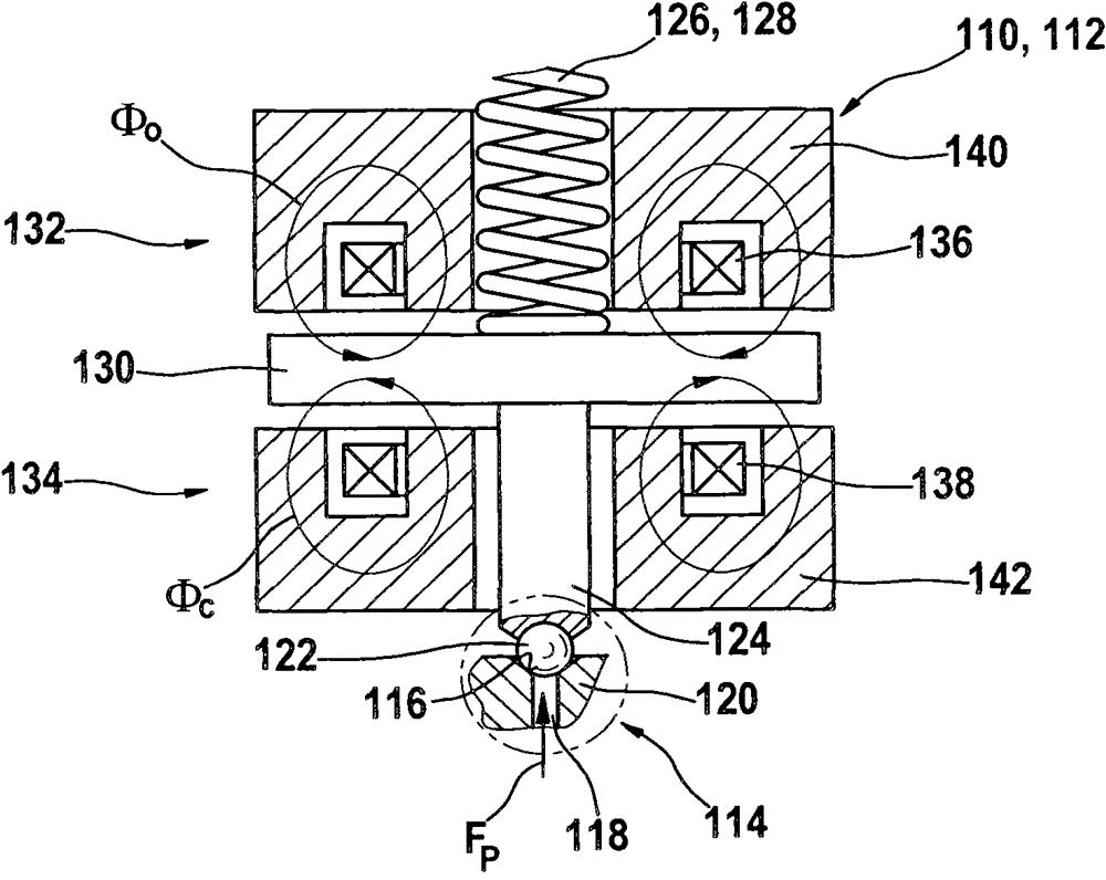
[0028] exist Figures 1 to 4B Various different embodiments of the hydraulic valve 110 that may be used in the fuel injector 112 are shown in . Other portions of fuel injector 112 are not shown in the drawings. Hydraulic valve 110 can be accommodated, for example, in an injector housing (not shown) of fuel injector 112 in which, for example, an injection valve element can also be supported. Each hydraulic valve 110 has a valve region 114 with a valve seat 116 and a valve bore 118 . The valve seat 116 and the valve opening 118 can be formed, for example, in an injector body 120 , which is only shown schematically. The valve opening 118 can, for example, open directly or indirectly into a control chamber of the fuel injector 112 , via which the stroke of the injection valve element can be controlled. Furthermore, the hydraulic valve 110 has a closing element 122 in the valve region 114 , which in the exemplary embodiment shown is embodied as a ball. In principle, however, ot...


PUM


Abstract

The invention relates to a hydraulic valve (110) for use in a fuel injector (112) for injecting fuel into a combustion chamber of an internal combustion engine. The hydraulic valve (110) includes at least one regulating member (124) and also includes at least one first electromagnetic actuator (132) and at least one second electromagnetic actuator (134). The first electromagnetic actuator (132) and the second electromagnetic actuator (134) are arranged to act on the adjusting member (124) with force directions opposite to each other.

Description

technical field [0001] The present invention relates to a known fuel injector for injecting fuel into a combustion chamber of an internal combustion engine. In particular, this can be a combustion chamber of a self-igniting internal combustion engine. Such fuel injectors are usually based on an injection valve element that releases or closes one or more injection holes. The movement of the injection valve element is usually controlled by one or more hydraulic valves. The hydraulic valves in turn may be controlled directly or indirectly through one or more actuators. This invention relates in particular to fuel injectors that use electromagnetic actuators as their actuators. Such fuel injectors are also referred to below as electromagnetic injectors. In the case of electromagnetic injectors, the opening of the hydraulic valve is usually achieved by the build-up of force during energization of the electromagnetic circuit of at least one electromagnetic actuator. By contrast,...

Claims


Application Information

Patent Timeline
Patent Type & Authority Patents(China)
IPC IPC(8): F02M51/06F16K31/06
CPCF02M63/0063F02M51/0617F02M63/0015
Inventor M·门尼肯M·拜尔
Owner ROBERT BOSCH GMBH
Why Eureka
Try Eureka