Exposure control method and device

A technology of exposure control and exposure parameters, which is applied in the field of image processing and can solve problems such as poor image exposure effect and single function of the capture machine

Active Publication Date: 2010-11-24
HANGZHOU HIKVISION DIGITAL TECH
View PDF0 Cites 37 Cited by
  • Summary
  • Abstract
  • Description
  • Claims
  • Application Information

AI Technical Summary

Problems solved by technology

[0004] The purpose of the embodiment of the present application is to provide an exposure control method and device applied in a capture machine to solve the problems in the prior art that the capture machine adopts fixed exposure parameters resulting in poor image exposure effect and the capture machine has a single function

Method used


Image

  • Exposure control method and device
  • Exposure control method and device
  • Exposure control method and device

Examples


no. 1 example

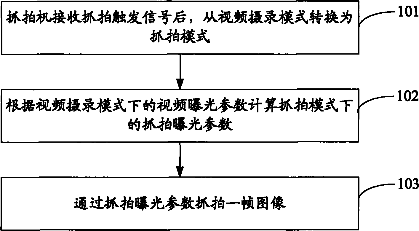
[0054] see figure 1 , is the flow chart of the first embodiment of the exposure control method of the present application:

[0055] Step 101: After the capture machine receives the capture trigger signal, it switches from the video recording mode to the capture mode.

[0056] Step 102: Calculate the snapshot exposure parameter in the snapshot mode according to the video exposure parameter in the video recording mode.

[0057] Specifically, obtain the preset slowest shutter speed, calculate the capture shutter speed according to the slowest shutter speed and the shutter speed in the video recording mode, and calculate the capture gain according to the shutter speed and gain in the video recording mode, The snapshot shutter speed and the snapshot gain are the snapshot exposure parameters. Further, the snapshot shutter speed and the snapshot gain can also be corrected by a preset correction coefficient (including a maximum gain value, etc.).

[0058] Step 103: Capture a frame of ...

no. 1 example

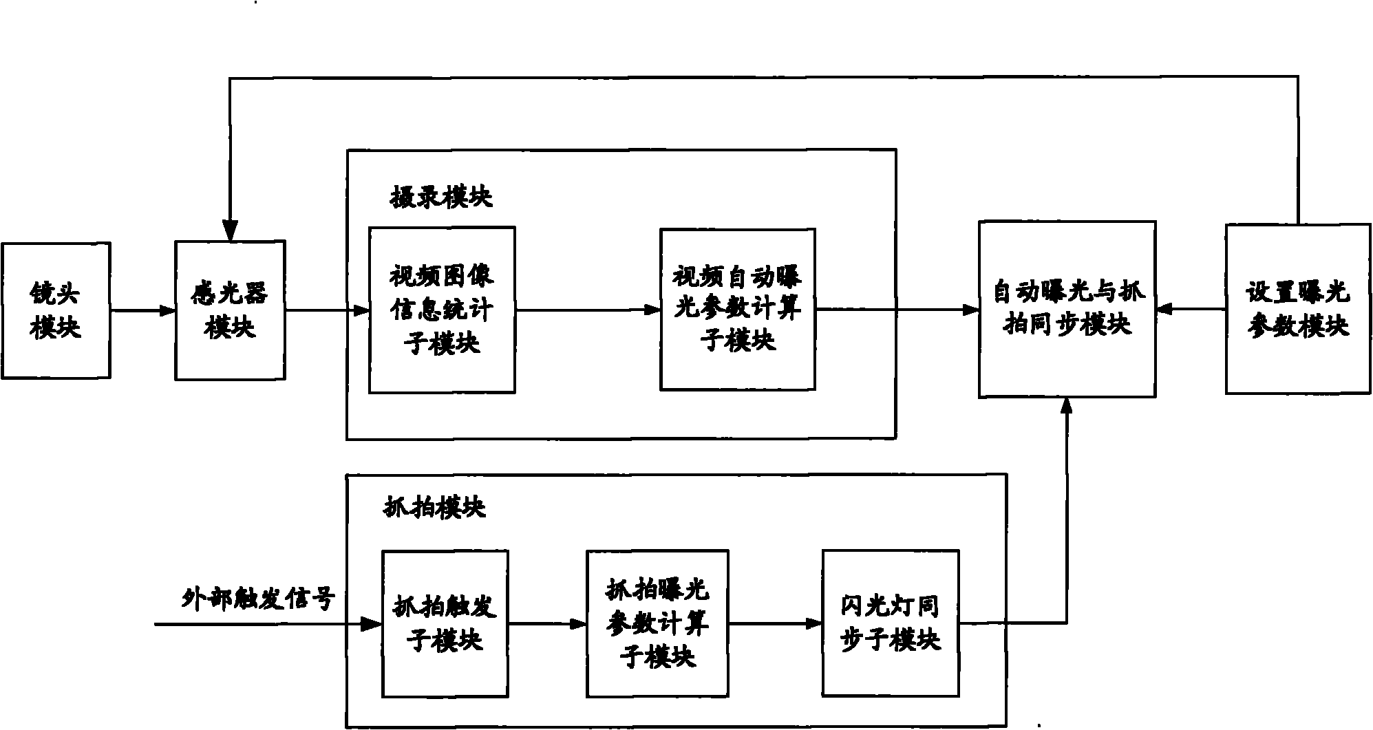
[0107] see Figure 4 , which is a block diagram of the first embodiment of the exposure control device of the present application:

[0108] The exposure control device includes: a conversion unit 410 , a calculation unit 420 and a capture unit 430 .

[0109] Wherein, the conversion unit 410 is configured to switch from the video recording mode to the capture mode after the capture machine receives the capture trigger signal;

[0110] A calculation unit 420, configured to calculate the capture exposure parameters in the capture mode according to the video exposure parameters in the video recording mode;

[0111] The capture unit 430 is configured to capture a frame of image according to the capture exposure parameters.

no. 2 example

[0112] see Figure 5A , which is a block diagram of the second embodiment of the exposure control device of the present application:

[0113] The exposure control device includes: a conversion unit 510 , a calculation unit 520 , an acquisition unit 530 , a correction unit 540 , a capture unit 550 and a recording unit 560 .

[0114] Wherein, the conversion unit 510 is configured to switch from the video recording mode to the capture mode after the capture machine receives the capture trigger signal;

[0115] A calculation unit 520, configured to calculate the capture exposure parameters in the capture mode according to the video exposure parameters in the video capture mode;

[0116] The acquiring unit 530 is configured to acquire a reference captured image before capturing the one frame of image, the video exposure parameter in the video recording mode corresponding to the reference captured image is the video in the video recording mode corresponding to the one frame of imag...


PUM


Abstract

The embodiment of the invention discloses an exposure control method and device which are used in a candid camera with a video recording mode and a candid mode. The method comprises the following steps: after receiving a candid trigger signal, the candid camera converts the video recording mode to the candid mode; the candid exposure parameter in the candid mode is calculated according to a video exposure parameter in the video recording mode; and one frame of candid image is shot according to the candid exposure parameter. The candid camera in the embodiment of the invention has double functions of video recording and candid so that the candid exposure parameter of any moment can be calculated according to the video exposure parameter; as the video exposure parameter is characterized by changing according to the physical environment, the calculated candid exposure parameter can change to adapt to the environment and the exposure quality of the candid image can be increased; and when the candid function of the candid camera in the embodiment of the invention is not triggered, the candid camera can perform real-time recording of the video image, thus the double functions of the candid camera can be realized.

Description

technical field [0001] The present application relates to the technical field of image processing, and in particular to an exposure control method and device applied in a camera. Background technique [0002] A camera is a device that is triggered by an event at a specific time to capture the current scene to obtain a close-up image of the current event. The camera is usually used in the field of traffic monitoring, such as capturing road speeding, toll checkpoints, and vehicles that violate traffic rules. Wait. During the capture process, due to the large change in the light brightness range of the natural scene, its dynamic range can reach 160dB, which is far greater than the dynamic range of ordinary digital cameras (about 55dB), so it is necessary to perform exposure control during the capture process. Appropriate exposure parameters are obtained, and the exposure parameters generally include aperture parameters, shutter parameters, gain parameters, and the like. In pr...

Claims


Application Information

Patent Timeline
Patent Type & Authority Applications(China)
IPC IPC(8): G03B7/00H04N5/225
Inventor 陈军张铧铧葛路烨徐鹏胡扬忠邬伟琪
Owner HANGZHOU HIKVISION DIGITAL TECH
Why Eureka
Try Eureka