Rotary combined device

A combination device and rotation direction technology, applied in the direction of electromechanical devices, electric components, casings/covers/supports, etc., can solve the problems of lack of sealing structure, reduced lubricating performance of self-lubricating bearings 11, low oil conduction efficiency, etc.

Inactive Publication Date: 2010-11-24
NS MICRO MOTOR TECH CORP
View PDF3 Cites 1 Cited by
  • Summary
  • Abstract
  • Description
  • Claims
  • Application Information

AI Technical Summary

Problems solved by technology

[0005] Although the above two designs can make the rotating shaft 12 rotate, the lubricating oil between the self-lubricating bearing 11 and the rotating shaft 12 is guided by the spiral groove 13 (or channel 14) and flows downward, but the spiral The flow path of the groove 13 (or groove 14) is quite long, which is almost equal to the overall length of the self-lubricating bearing 11. Therefore, the oil conduction path and the time spent will be long, so that the oil conduction efficiency is low
[0006] Furthermore, the top surface of the self-lubricating bearing 11 is designed to be flat. Once the lubricating oil climbs up from between the self-lubricating bearing 11 and the rotating shaft 12 and escapes from the gap, since the self-lubricating bearing 11 lacks Sealing structure, it is easy to make lubricating oil splash upwards and relatively reduce the amount of stored oil, so that the lubricating performance of the self-lubricating bearing 11 is reduced

Method used


Image

  • Rotary combined device
  • Rotary combined device
  • Rotary combined device

Examples


Embodiment Construction

[0054] The present invention will be described in detail below in conjunction with the accompanying drawings and embodiments. Before the present invention is described in detail, it is noted that in the following description, similar elements are denoted by the same numerals.

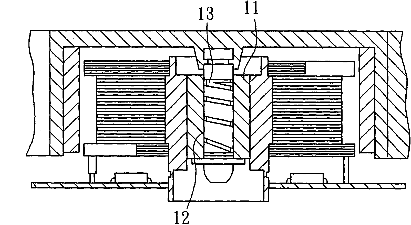
[0055] see also Figure 3 to Figure 5 , the first preferred embodiment of the rotary combination device 2 of the present invention is applied in such as figure 1 The technical field of the fan motor shown, and the fan motor generally includes components such as housing base, fan wheel, stator, magnet ring, circuit board, etc. figure 1 The content shown can be easily known, therefore, it will not be described in detail and specially drawn schematically.

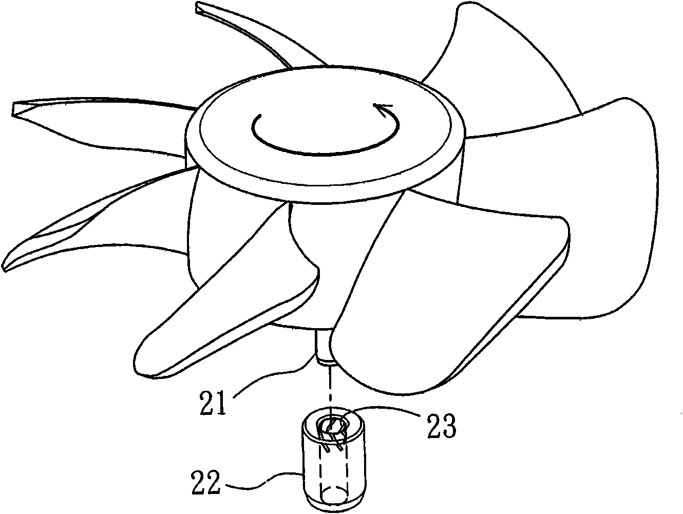
[0056] The main structure of the rotating combination device 2 is specifically described below, and the rotating combination device 2 includes a image 3 , Figure 4 (counterclockwise direction indicated by the middle arrow) rotating shaft 21 and a ...


PUM


Abstract

The invention provides a rotary combined device, which is applied in the technical field of fan motors. The rotary combined device comprises a rotary shaft and a self-lubricating bearing sleeved on the rotary shaft, wherein a plurality of alternately arranged inside chutes are reserved on the self-lubricating bearing and each inside chute is obliquely extended downwards in a specified rotation direction corresponding to the rotary shaft from the top to the bottom of the chute. When the rotary shaft rotates towards the specified rotation direction, lubricating oil is guided by the inside chutes to flow downwards and accumulate; and the lubricating oil spilled from a gap on the top is effectively baffled by a concave buffer zone formed on the top of the self-lubricating bearing so as to avoid the decreasing of oil and then improve the lubricating property and prolong the service life. In addition, because the vertical distance of the inside chutes is relatively short, oil guide efficiency can be improved.

Description

technical field [0001] The invention relates to a rotary combination device, in particular to a rotary combination device for a fan motor. Background technique [0002] The existing self-lubricating bearings or oil-impregnated bearings maintain lubrication and reduce friction loss through lubricating oil. Therefore, how to prevent the loss of lubricating oil and improve the friction loss of self-lubricating bearings or oil-impregnated bearings has become a major issue. In order to prevent the bearing from losing lubricating oil, gaskets are generally provided at both ends of the bearing to prevent the internal lubricating oil from flowing out. However, such a design can only delay the outflow of internal lubricating oil, but cannot effectively prevent the outflow of lubricating oil. Therefore, it is necessary to further use other methods to prevent self-lubricating bearings from losing lubricating oil. technology disclosed. [0003] see figure 1 , which is a combined stru...

Claims


Application Information

Patent Timeline
IPC IPC(8): H02K5/16
Inventor 洪银农
Owner NS MICRO MOTOR TECH CORP
Why Eureka
Try Eureka