Drainage mechanism, heat exchange unit and heat exchange equipment

A heat exchange unit and heat exchange tube technology, applied in heat exchange equipment, lighting and heating equipment, indirect heat exchangers, etc., can solve the problems of increased cost and structural volume, complex oil return control, poor system reliability, etc., to achieve Improved heat exchange efficiency, convenient oil return, and high heat exchange efficiency

Pending Publication Date: 2021-04-27
HANGZHOU SHENSHI ENERGY CONSERVATION TECH
View PDF0 Cites 0 Cited by
  • Summary
  • Abstract
  • Description
  • Claims
  • Application Information

AI Technical Summary

Problems solved by technology

[0003] Therefore, the technical problem to be solved by the present invention is that the shell-and-tube heat exchanger in the prior art has increased cost and structural volume due to the addition of additional oil return pipelines and controllers, and the oil return control is complicated, and the system reliability is relatively low. poor defect

Method used


Image

  • Drainage mechanism, heat exchange unit and heat exchange equipment
  • Drainage mechanism, heat exchange unit and heat exchange equipment
  • Drainage mechanism, heat exchange unit and heat exchange equipment

Examples


Embodiment 1

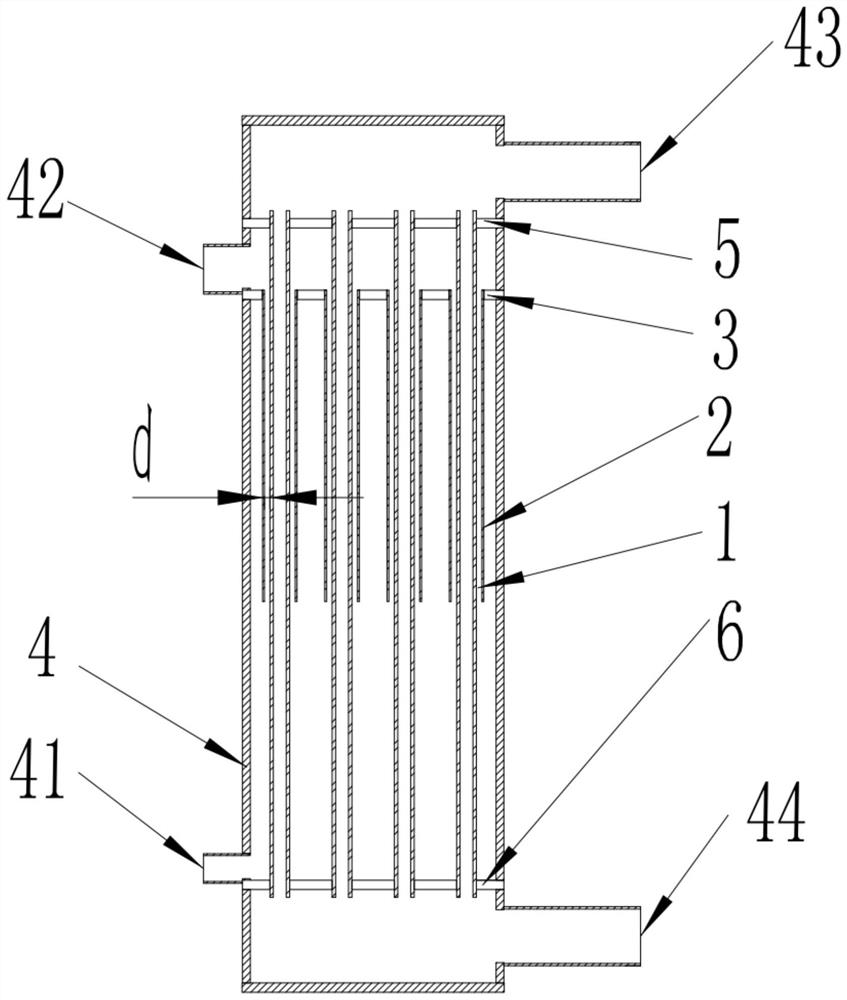
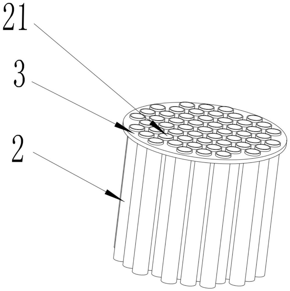
[0049]This embodiment provides a drainage mechanism for mounting with a heat transfer tube 1, such asFigure 1 to 3As shown, including: the drainage 2, the drainage 2 extends in the longitudinal direction of the heat transfer pipe 1; the drainage portion 2 has a drainage surface 21 disposed toward the outer wall surface of the heat transfer tube 1, and the drainage surface 21 is adapted to heat the heat pipe 1. The outer wall surface forms a climbing gap d.

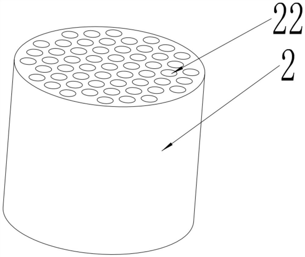
[0050]Specifically, in this embodiment, iffigure 2 As shown, the drainage 2 is a tubular structure. When the actual installation is used, the heat transfer tube 1 is disposed inside the tubular structure, so that the inner wall surface of the tubular structure is a drainage surface 21; for example, the tubular body can be a round tube. The circular tube is a closed surface along the cross section of the radial direction of the heat collecting pipe 1, and the present embodiment selects the closed surface as a circular tubular struct...

Embodiment 2

[0056]This embodiment provides a heat exchange unit including: housing 4, heat exchange mechanism, and drainage mechanism provided in Example 1. Wherein, the housing 4 has a refrigeration cavity, the refrigeration cavity suitable for flowing refrigeration cycle medium; the heat exchange mechanism has a heat transfer tube, the heat transfer pipe is mounted in the housing 4, the heat transfer tube 1 Suitable for the convergence of the cooling medium; the drainage mechanism is mounted within the housing 4, the diaphragm surface forms a climbing gap d of the refrigeration cycle medium climbing with the outer peripheral wall surface of the heat transfer tube 1.

[0057]The heat transfer tube 1 provided in this embodiment includes a tubular body and a first wing portion, wherein the first wing portion is disposed on the outer peripheral wall surface of the tubular body. That is, the heat transfer pipe 1 is an outer tube.

[0058]Of course, in other alternative embodiments, the heat transfer tub...

Embodiment 3

[0069]This embodiment provides a heat exchange device including the heat exchange unit, a press unit, and a pumping unit in Example 2. Wherein, the first refrigerant interface and the second refrigerant interface of the housing are respectively connected, and the pressure transfer unit is adapted to flow into or out of the refrigeration cycle medium; The two ends of the pumping unit are respectively coupled to the first cooling agent interface of the housing, respectively, the pumping unit being adapted to flow or flow into the cooling medium to the heat transfer tube. In this embodiment, the pressure transfer unit is a compressor and a refrigeration cycle loop.


PUM


Abstract

The invention discloses a drainage mechanism, a heat exchange unit and heat exchange equipment. The drainage mechanism comprises a drainage piece, wherein the drainage piece extends in a length direction of a heat exchange tube; the drainage piece is provided with a drainage surface arranged towards the outer side wall face of the heat exchange tube, and a climbing gap is formed between the drainage surface and the outer side wall surface of the heat exchange tube. The climbing gap is formed between the drainage surface and the heat exchange tube, so that compared with other positions, the part with the climbing gap has the advantages that a medium flows faster, for example, oil drops of lubricating oil and a refrigerant in a gas state flow to an outlet along the climbing gap, so that it is ensured that a mixture of the refrigerant and the lubricating oil passing through the heat exchanger still flow out of the outlet of the heat exchanger together, and therefore, on one hand, the inner volume of the heat exchanger is reduced, and on the other hand, oil loss of the system is effectively avoided.

Description

Technical field[0001]The present invention relates to the technical field of heat exchange equipment, and more particularly to a drainage mechanism, a heat exchange unit, and a heat exchange device.Background technique[0002]In the refrigeration system, the housing heat exchanger is used as the refrigeration system evaporator, and the refrigerant evaporates into a gas in the cavity in the housing, and it is necessary to flow from the air outlet in the upper portion of the heat exchanger, and the lubricating oil carried in the refrigerant Then stay within the cavity of the container, cannot flow out as the gas, so that the compressor cannot be returned, resulting in a system failure. Therefore, there is often an additional oil return line and controller, but if the above-described manner is used to return oil, the cost and volume will greatly increase, and the control is complex, the reliability of the structure is decreased.Inventive content[0003]Accordingly, the technical problem to...

Claims


Application Information

Patent Timeline
Patent Type & Authority Applications(China)
IPC IPC(8): F28D7/00F28D7/02F28F1/10F28F7/00F25B39/00F25B31/00
CPCF25B31/004F25B39/00F28D7/00F28D7/02F28F1/10F28F7/00
Inventor 赵博吕志锡
Owner HANGZHOU SHENSHI ENERGY CONSERVATION TECH
Why Eureka
Try Eureka