Easily loaded and unloaded getter device for reducing evacuation time and contamination in a vacuum chamber and method for use of same

a vacuum chamber and getter technology, applied in the direction of machines/engines, flexible member pumps, positive displacement liquid engines, etc., can solve the problems of reducing the quantity of residual adsorbed gases on the surface of the chamber, requiring substantial modifications, and powders that cannot be applied to metallic supports only, etc., to achieve easy loading and unloading, reduce evacuation time and contamination, and high surface area

Inactive Publication Date: 2005-02-22
SAES GETTERS SPA
View PDF12 Cites 5 Cited by
  • Summary
  • Abstract
  • Description
  • Claims
  • Application Information

AI Technical Summary

Benefits of technology

The present invention provides an easily loaded and unloaded getter device for reducing evacuation time and contamination in a vacuum chamber. The getter device comprises a getter body having essentially the shape of a substrate used in a deposition process. Forming the getter body to have the same shape as a substrate allows the getter device to be loaded and unloaded with respect to a chamber by existing automatic handling equipment already configured to load and unload substrates. Further, the shape allows the getter device to be placed into a substrate carrier for introduction into a processing system. Further still, most substrates are broad and thin, and a getter device having such a shape will advantageously have a high surface area per unit weight of getter material. Some embodiments of the present invention are shaped like semiconductor wafers use in semiconductor fabrication, while others are shaped like the rectangular substrates used in the production of flat panel displays.
A getter device of the present invention is preferably formed of a powder of at least one getter material. Fabrication from a powder provides a high specific surface area for improved gettering capacity. Additional embodiments of the present invention are directed to a getter body comprising a support and a first getter layer formed of at least one deposit of a getter material on a first face of the support. In further embodiments the getter body further comprises a second getter layer formed of at least one deposit of a getter material on a second face of the support. Still other embodiments further include a first uncoated rim portion on the first face of the support and a second uncoated rim portion on the second face of the support. The support is advantageous because it provides mechanical strength to the getter body. Uncoated rim portions allow getter devices of the present invention to be manipulated by automated handling equipment typically configured to handle substrates by their edges. Therefore, by leaving rim portions uncoated, the clamps, tangs, and guides used by automated handling equipment to transfer substrates will not come into contact with the getter layers and create particulate contamination.
Getter devices of the present invention provide several advantages over the prior art. Getter devices of the present invention do not need to be permanently mounted within a process chamber. Consequently, getter devices of the present invention may be readily used in conjunction with any vacuum chamber configured to accept a substrate, regardless of whether the chamber already includes a getter pump. An easily transportable getter device also removes the need for mounting brackets, complex shielding to protect the getter material of the device, and additional heaters to periodically activate the getter material. Eliminating brackets, shields, and heaters allows the chamber to have a smaller internal volume so it can be more rapidly evacuated to a desired vacuum level. Removing these components can simplify the design and manufacture of vacuum chambers and therefore help reduce their cost. Further, an easily transportable getter device can be removed from a chamber without having to resort to a time consuming tear-down procedure that exposes the chamber to the ambient atmosphere and thereafter requires a lengthy re-assembly, bake-out, and pump-down.
The present invention also provides a method for increasing the yield of a manufacturing process that includes the deposition of a thin layer in a vacuum chamber. The method comprises introducing a getter device into the vacuum chamber before or during evacuation with the same automated substrate handling equipment used for transferring substrates. An unactivated getter device can be loaded before evacuation begins, and then after a pressure of about 10−3 mbar or less has been achieved the getter material can be activated with heaters configured to heat a substrate. An activated getter device can be loaded after a pressure of about 10−3 mbar or less has been achieved in the chamber. Some embodiments of the method include activating the getter material in a separate activation chamber before the getter device is loaded into the vacuum chamber. Further embodiments of the method provide for the use of a getter device in a vacuum chamber where the total pressure is above about 10−3 mbar, provided that the sum of the partial pressures of all reactive gases remains below about 10−3 mbar and the balance of the atmosphere within the chamber comprises non-reactive gases such as noble gases.
The method of the invention is advantageous because it allows the pressure within a vacuum chamber both to be reduced to a preset value more quickly and to be reduced to a lower base pressure. A lower base pressure results in lower impurity levels within the vacuum chamber leading to higher quality films and higher production yields. The method is also advantageous because it may be used with equipment that isn't presently configured to include a getter pump.

Problems solved by technology

These defects are most commonly due to the inclusion of impurity atoms or molecules within the deposited layers.
Thus, increasing the pumping speed during baking further reduces the quantity of residual adsorbed gases on surfaces within the chamber.
The deposition of powders can be carried out by cold rolling, as is well known in the field of powder metallurgy, however powders can only be applied to metallic supports.
A significant disadvantage of the foregoing prior art is that substantial modifications are often required in order to configure a processing chamber to accommodate such getter devices and associated hardware such as heaters and shields.
These modifications increase the size, the complexity, and the cost of a vacuum chamber, and increased size generally implies an increased internal volume and a longer evacuation time.
Further, getter devices of the prior art are not easily removed from a chamber without opening it to the ambient atmosphere.
It is further well known that activated getter materials cannot be exposed to partial pressures of reactive gases higher than about 10−3 mbar, and that unactivated getter materials cannot be activated at such pressures, because either act can result in the combustion of the getter material.

Method used


Image

  • Easily loaded and unloaded getter device for reducing evacuation time and contamination in a vacuum chamber and method for use of same
  • Easily loaded and unloaded getter device for reducing evacuation time and contamination in a vacuum chamber and method for use of same
  • Easily loaded and unloaded getter device for reducing evacuation time and contamination in a vacuum chamber and method for use of same

Examples


example 1

The pressure in a PVD deposition chamber was continuously monitored while a pump-down cycle was performed. The measured pressure in the chamber during this cycle is shown in FIG. 9 as curve 1. The chamber included a pedestal supporting a sample-holder and further included an internal electrical resistance heater. The chamber also included two quartz lamps located on two opposing side walls. A rotary pump and a cryogenic pump were connected to the chamber by a port to perform the pump-down. In order to measure pressures in the chamber below about 10−5 mbar a Bayard-Alpert manometer was employed.

At the beginning of the test the chamber was sealed and pumping was initiated. Approximately a half hour into the test, when the pressure in the chamber reached a value of about 10−6 mbar, a baking procedure was performed by heating the interior of the chamber with the quartz lamps and heating the electrical resistance heater to 500° C. After a two hour bake the chamber was allowed to cool whi...

example 2

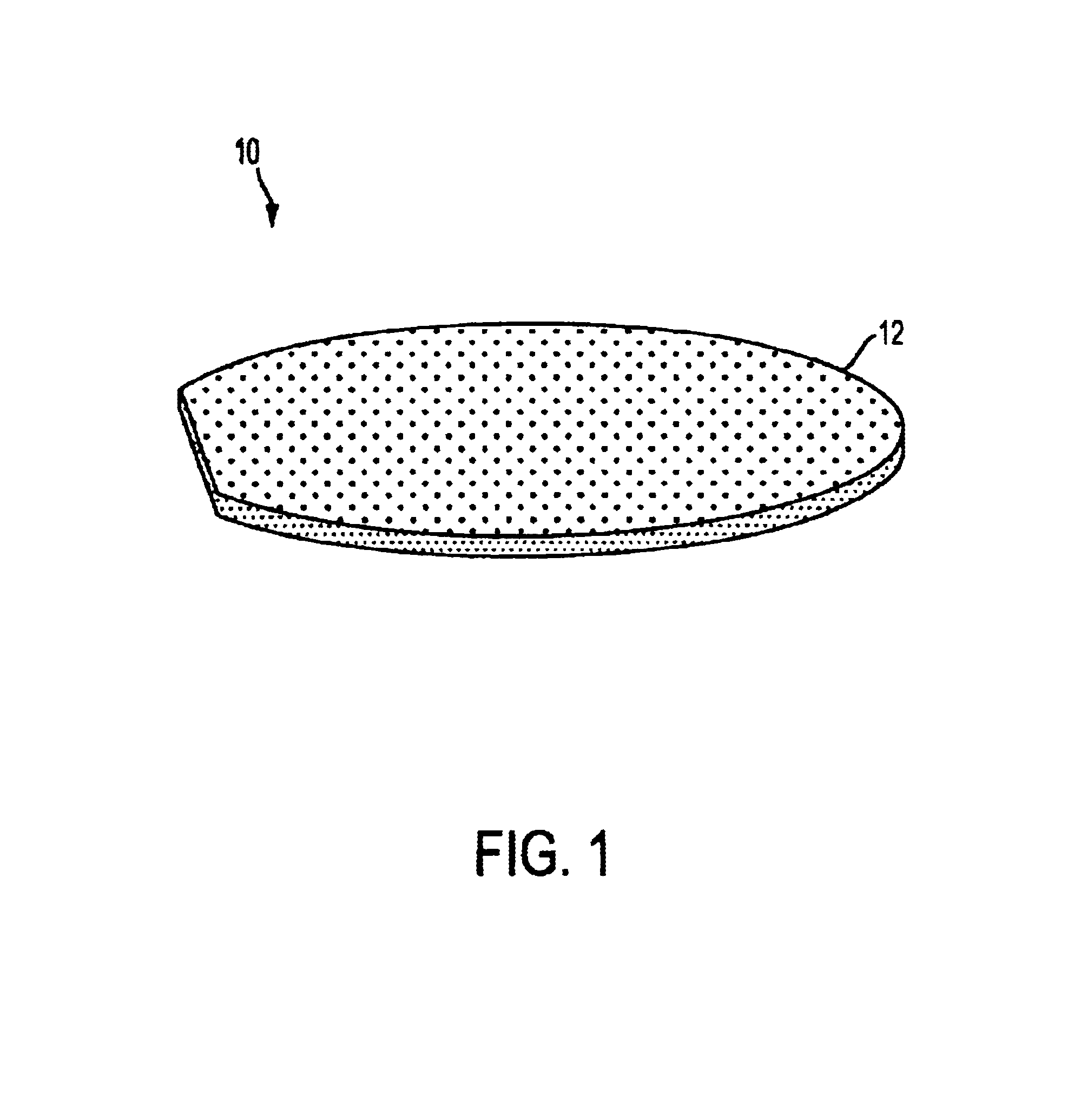
The pressure in the PVD deposition chamber used in Example 1 was continuously monitored while a pump-down cycle using a getter device of the present invention was performed. The measured pressure in the chamber during this cycle is shown in FIG. 9 as curve 2. Initially, a non-activated getter device was placed on the sample holder within the chamber. The getter device consisted of a silicon wafer support having a diameter of about 200 mm and a deposit of getter material on one face. The getter material used was St 121, described above, and was deposited by screen printing to create a layer approximately 150 μm thick. The evacuation procedure described in Example 1 was then repeated. During the baking procedure, the temperature of the getter device was raised to about 500° C., primarily by the internal electrical resistance heater. The getter material was thus activated during the baking.

From Curve 2 in FIG. 9 it can be seen that during the bake the pressure in the chamber increased,...


PUM

PropertyMeasurementUnit
pressureaaaaaaaaaa
thicknessesaaaaaaaaaa

Abstract

A getter device is shaped like a substrate used in a deposition process. Embodiments of the device include a powdered getter material coated onto one or both sides of a support with a narrow rim portion left uncoated so that the device can be manipulated by automatic handling equipment. A method for using the getter device includes providing a vacuum chamber and automatic handling equipment, loading the device into the chamber, reducing the chamber pressure to a desired value by using the getter device in conjunction with an external pump, removing the getter device and replacing it with a substrate, and depositing a thin film on the substrate. The getter device can be in an activated state when loaded into the chamber, or it can be activated after being loaded by employing heating equipment ordinarily used to heat substrates placed in the chamber. The getter material of the device may also be activated in a separate activation chamber before the getter device is loaded into the vacuum chamber.

Description

BACKGROUND OF THE INVENTION1. The Field of the InventionThe present invention provides a getter device advantageously shaped like a substrate for use in a thin film deposition system and a method for its use.2. BackgroundProcesses for depositing thin films onto substrates are widely used in the manufacture of a wide array of commercial products. Examples of these processes include the fabrication of integrated electronic circuits (ICs) in which circuits are formed on a semiconductor substrate; the manufacture of data storage media, such as compact disks (CDs), where a thin layer of aluminum is deposited onto a substrate of a transparent plastic; the production of computer hard disks where a magnetic material is deposited onto a substrate such as aluminum; and the production of flat panel displays in which active elements are commonly created on glass substrates. Processes for depositing thin layers are also being adapted to the developing field of micromechanical devices, where micr...

Claims


Application Information

Patent Timeline
Patent Type & Authority Patents(United States)
IPC IPC(8): C23C14/56F04B37/04F04B37/00C23C14/00C23C14/54B01J19/00C23C16/44
CPCF04B37/04C23C14/564
Inventor CONTE, ANDREAMAZZA, FRANCESCOMORAJA, MARCO
Owner SAES GETTERS SPA
Why Eureka
Try Eureka