Rotating joint of rubber tube of oiling machine

A technology of rotary joint and fuel dispenser, which is used in liquid distribution, conveying or transfer devices, special distribution devices, packaging, etc., can solve the problems of high labor intensity, unfavorable sealing, scratching vehicles, etc., to reduce labor intensity and prevent leakage. Oil, the effect of avoiding seal failure

Pending Publication Date: 2018-12-21
河南欧科机电设备有限公司
View PDF0 Cites 0 Cited by
  • Summary
  • Abstract
  • Description
  • Claims
  • Application Information

AI Technical Summary

Problems solved by technology

[0002] At present, the connection between the oil gun hose and the fuel dispenser in the gas station is fixedly connected, and the seal is sealed with an O-shaped rubber ring. The connection between the gun hose and the fuel dispenser is a fixed connection. Affected by the hardness of the hose and its own weight, more than one turn of the coil will cause stress on the joint between the grease gun hose and the fuel dispenser. Long-term force is not conducive to sealing. The joint oil leakage caused by the oil gun hose coil hanging caused unnecessary losses; because the connection angle between the oil gun hose and the fuel dispenser is fixed, specific limit measures need to be set for the oil gun hose coil hanging. , the labor intensity of the refueling staff is relatively high, and in actual operation, there are often phenomena such as the oil gun hose coil not being in place, the parking position of the refueling customer needs to pull the oil gun hose, etc., all of which cause the oil gun hose and the fuel dispenser to be stressed. It is easy to cause sealing failure and oil leakage loss, and there are even problems such as the oil gun hose mopping the floor being crushed by the vehicle, fouled, and scratching the vehicle when refueling in reverse; high

Method used


Image

  • Rotating joint of rubber tube of oiling machine
  • Rotating joint of rubber tube of oiling machine
  • Rotating joint of rubber tube of oiling machine

Examples


Embodiment Construction

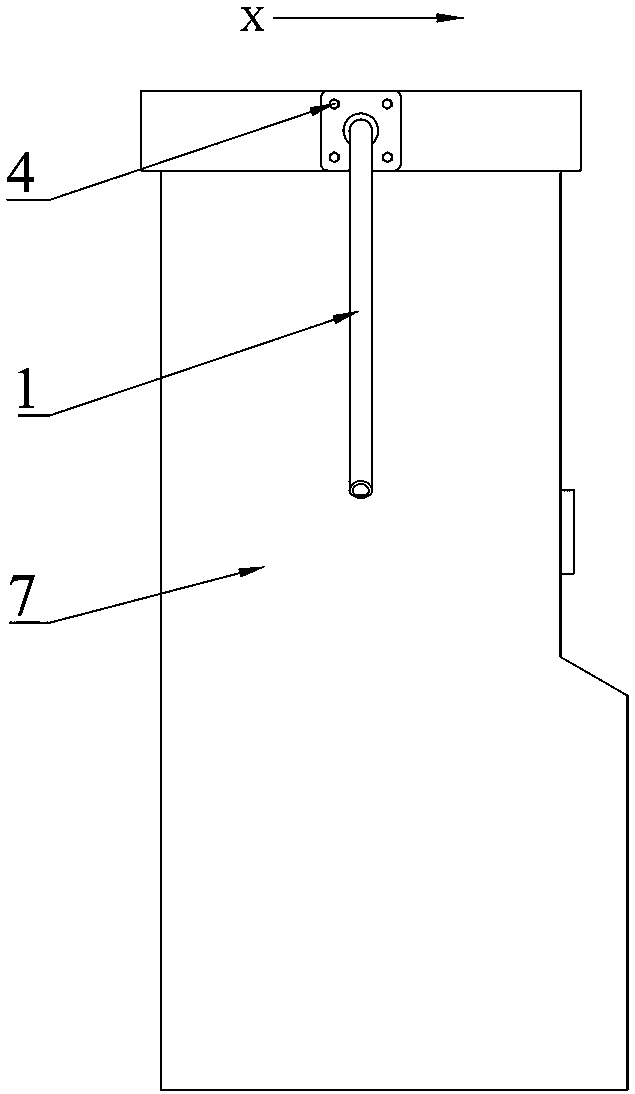
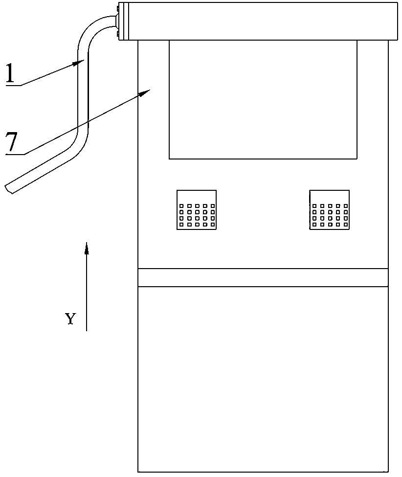
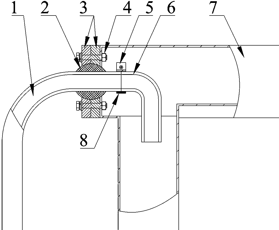
[0031] A fuel dispenser rubber hose rotary joint, the structure of which is as follows Figure 1~3 As shown, it includes an oil gun rubber hose 1 and a joint body fixedly connected to the fuel dispenser 7 . The joint body includes a spherical joint 2. The spherical joint 2 is a spherical structure with a cylindrical through hole on the central axis. The spherical joint 2 is symmetrically provided with two joint sleeves 3 with arc-shaped chambers along the vertical plane. The structures of the joint sleeves 3 are exactly the same. The arc chambers of the two joint sleeves 3 cooperate to form the accommodation cavity of the spherical joint 2. The outer surface of the spherical joint 2 is rotatably matched with the inner surface of the accommodation cavity. The spherical joint 2 is pinched from two directions and tightly merged. The accommodation cavity formed after the two joint sleeves 3 are tightly merged is in contact with the outer surface of the spherical joint 2 but does n...


PUM


Abstract

The invention belongs to the technical field of oiling machine auxiliary equipment, and particularly relates to rotating joint of a rubber tube of an oiling machine. The rotating joint comprises an oil gun rubber tube and a joint body, the joint body comprises a spherical joint, two joint sleeves with arc-shaped cavities are symmetrically arranged on the outer edge of the spherical joint along thevertical plane, the arc-shaped cavities of the two joint sleeves are matched to form a containing cavity of the spherical joint, the outer surface of the spherical joint is rotationally matched withthe inner surface of the containing cavity, the two joint sleeves are fixed on the outer wall of an oil outlet of the oiling machine through mounting bolt assemblies, the spherical joint is provided with a cylindrical through hole along the axis of the spherical joint, the oil gun rubber tube penetrates through the through hole and then extends into the oiling machine, the through hole is in interference fit with the oil gun rubber tube, the end of the oil gun rubber tube located in the oiling machine is connected with an oil conveying hose through a connecting hoop, the deflection angle of the spherical joint is -30 DEG C-30 DEG C, and the spherical joint rotates by 360 degrees along the axis of the spherical joint. The rotating joint is not only simple in structure, but also capable of effectively preventing oil leakage loss.

Description

technical field [0001] The invention belongs to the technical field of fuel dispenser auxiliary equipment, and in particular relates to a fuel dispenser rubber hose rotary joint. Background technique [0002] At present, the connection between the oil gun hose and the fuel dispenser in the gas station is fixedly connected, and the seal is sealed with an O-shaped rubber ring. The connection between the gun hose and the fuel dispenser is a fixed connection. Affected by the hardness of the hose and its own weight, more than one turn of the coil will cause stress on the joint between the grease gun hose and the fuel dispenser. Long-term force is not conducive to sealing. The joint oil leakage caused by the oil gun hose coil hanging caused unnecessary losses; because the connection angle between the oil gun hose and the fuel dispenser is fixed, specific limit measures need to be set for the oil gun hose coil hanging. , the labor intensity of the refueling staff is relatively hig...

Claims


Application Information

Patent Timeline
Patent Type & Authority Applications(China)
IPC IPC(8): B67D7/38
CPCB67D7/38
Inventor 梁大伟李伟
Owner 河南欧科机电设备有限公司
Why Eureka
Try Eureka