Heating system for vehicle

A technology for heating devices and vehicles, applied in vehicle parts, transportation and packaging, heating/cooling equipment, etc., can solve problems such as inability to heat and cold arms, and achieve the effects of eliminating discomfort, comfortable heating, and eliminating radiant heat.

Active Publication Date: 2010-11-24
PANASONIC CORP
View PDF3 Cites 3 Cited by
  • Summary
  • Abstract
  • Description
  • Claims
  • Application Information

AI Technical Summary

Problems solved by technology

[0004] However, in the above-mentioned prior art, the infrared rays radiated from the surface of the heat radiation member during heating can only irradiate the occupant's feet to the torso, so there is a problem of coldness from the head to the shoulders and to the arms during driving.
In addition, there is a problem that various parts cannot be sufficiently heated due to the limitation of the available electric power of the vehicle

Method used


Image

  • Heating system for vehicle
  • Heating system for vehicle
  • Heating system for vehicle

Examples


no. 1 approach

[0022] refer to figure 1 , figure 2 , the first embodiment of the present invention will be described.

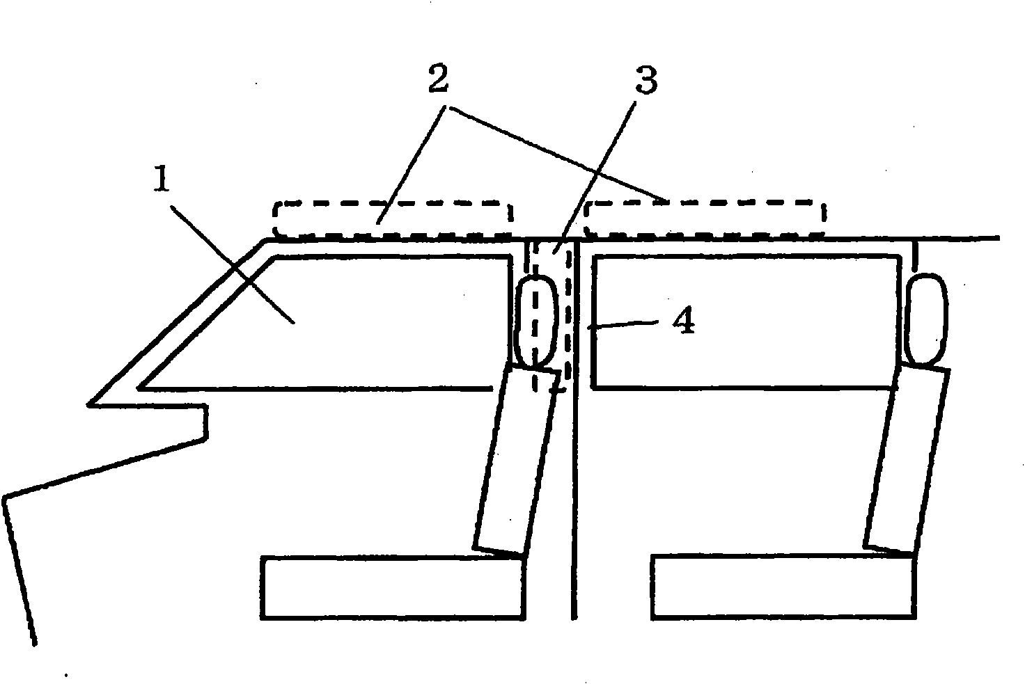
[0023] figure 1 It is an external view of the vehicle heater according to the first embodiment of the present invention. In the figure, a planar heating element 2 is arranged above a side glass 1 . The planar heating element 2 is arranged such that the heating surface faces the upper body from the head to the shoulders of the occupant sitting on the seat.

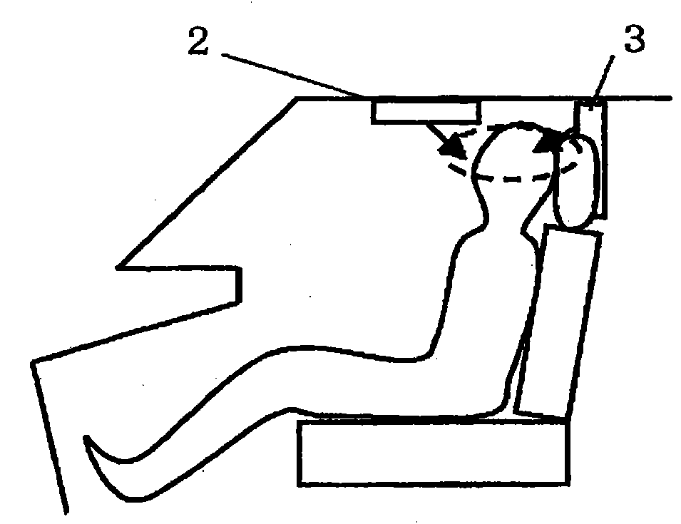
[0024] According to the above structure, such as figure 2 As shown, when the planar heating element 2 is energized, radiant heat can be used to heat the upper body of the front seat occupant. In particular, radiant heating as described above is effective during severe winters because the head is uncovered and exposed.

[0025] In addition, it is also possible to configure the disposition area of ​​the planar heating element 2 from the passenger's head to be arranged above the side glass 1, since the planar heatin...

no. 2 approach

[0029] refer to figure 1 , figure 2 , the second embodiment of the present invention will be described.

[0030] figure 1 It is an external view of the vehicle heater according to the first embodiment of the present invention. In the figure, the planar heating element 3 is disposed on the central column portion 4 . The planar heating element 3 is arranged such that the heating surface faces the upper body from the head to the shoulders of the occupant sitting on the seat.

[0031] According to the above structure, such as figure 2 As shown, when the planar heating element 3 is energized, the upper body of the front seat occupant can be heated by radiant heat.

[0032] In addition, the planar heating element may be disposed on the side pillar portion of the rear seat so that the upper body of the rear seat occupant can be heated.

[0033] In addition, a planar heating element may be disposed above the side glass 1 and the center pillar 4 so as to face the occupant's upp...

no. 3 approach

[0042] refer to image 3 , Figure 4 , the third embodiment of the present invention will be described.

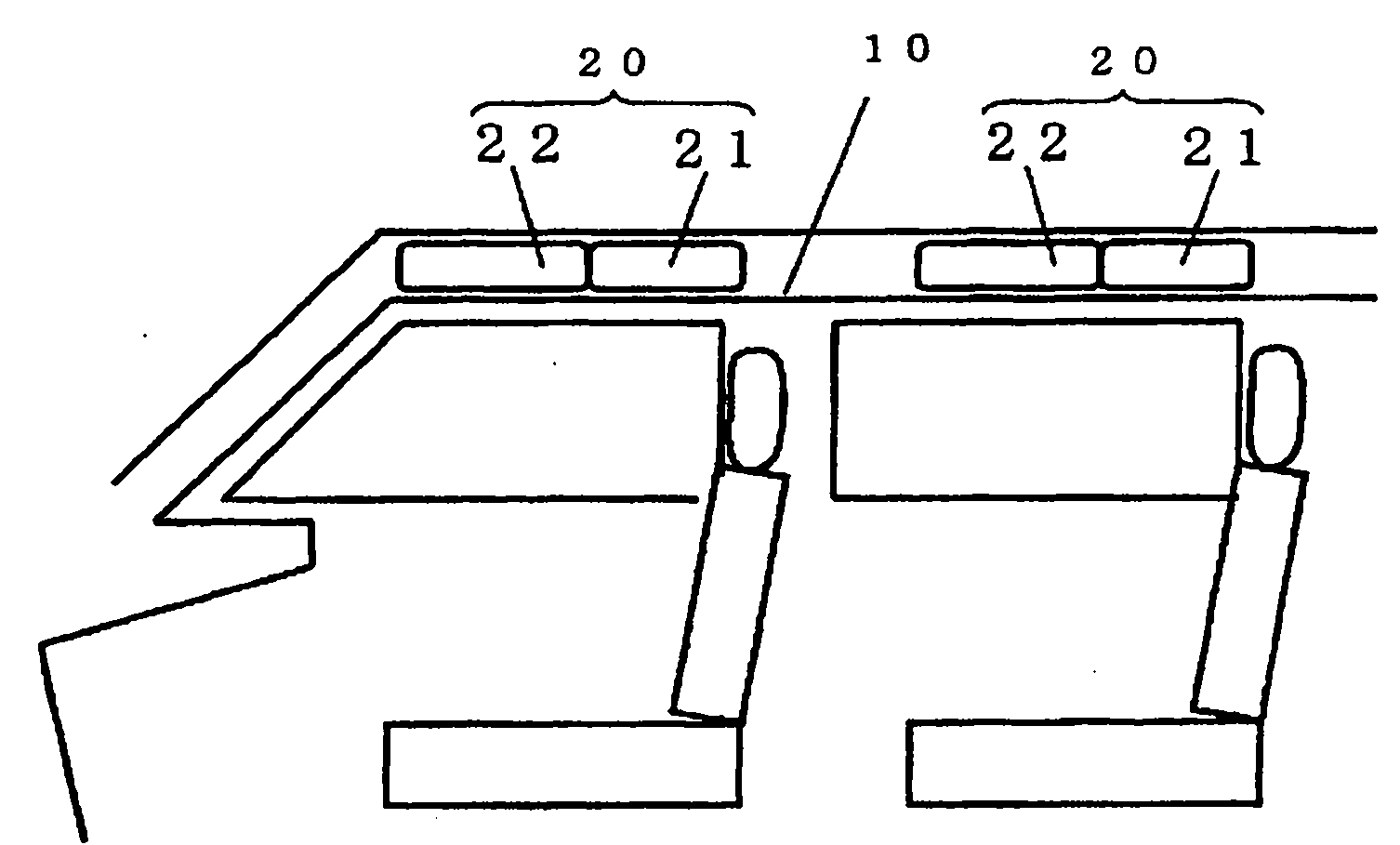
[0043] image 3 It is an external view of a vehicle heater according to a third embodiment of the present invention. In the figure, a planar heating element 20 is arranged on the top surface 10 . The planar heating element 2 is arranged such that the heating surface faces the portion from the head to the shoulders of the occupant sitting on the seat, and to the arms during driving.

[0044] According to the above structure, such as Figure 4 As shown, when the planar heating element 20 is energized, radiant heat can be used to heat the front seat occupant from the head to the shoulders, and to the arms during driving. In particular, radiant heating as described above is effective during severe winters because the head is uncovered and exposed.

[0045] In addition, when the temperature in the cabin is raised by heating, the radiant heat radiated to the head will cause ...


PUM


Abstract

A heating system for vehicle which can perform heating effectively by irradiating from the head to the shoulder of a person in a vehicle with infrared rays radiated from the surface of a heat radiation member at the time of heating. When a planar heating element (2) is arranged above the side glass, it is arranged to face the upper body of a person sitting in the seat from the head to the shoulder so that the upper body of a person in the front seat can be heated with radiation heat as a current is conducted through the planar heating element (2). When a planar heating element (3) is arranged at the center pillar portion, the upper body of a person in the front seat can be heated with radiation heat as a current is conducted through the planar heating element (3).

Description

technical field [0001] The invention relates to a heating device for vehicles. Background technique [0002] Conventionally, as such a vehicle heating device, a planar electric heater is arranged along the surface of an interior member in a vehicle cabin, and a heat radiation member made of a material with a high heat emissivity is arranged on the surface of the electric heater. Then, the heat radiation member is heated by heat generated by the electric heater, and infrared rays are radiated from the surface of the heat radiation member. The interior parts are: at least one of the lower part of the vehicle instrument panel located in the front part of the vehicle compartment, the lower part of the left and right door sides in the vehicle compartment, the left and right side parts of the center console in the vehicle compartment, and the back part of the front seat part (for example, Refer to Patent Document 1). [0003] Patent Document 1: Japanese Patent Laid-Open No. 2005...

Claims


Application Information

Patent Timeline
Patent Type & Authority Applications(China)
IPC IPC(8): B60H1/22B60H1/03
CPCB60H2001/2265B60H2001/00228B60H2001/2293B60H1/2218B60H1/2227
Inventor 日置一昭吉本弘次朝见直仁阿部宪生有马聪小西英昭荻野弘之近藤龙太
Owner PANASONIC CORP
Why Eureka
Try Eureka