Light projection device
A technology of light projection and projection position, which is applied to display devices, lighting devices, light sources, etc., and can solve problems such as inability to use an item search system and trouble for users
- Summary
- Abstract
- Description
- Claims
- Application Information
AI Technical Summary
Problems solved by technology
Method used
Image
Examples
Embodiment approach 1
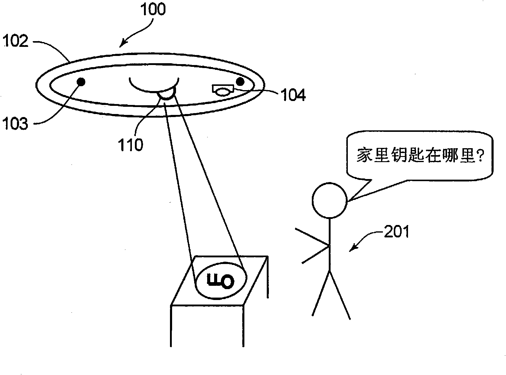
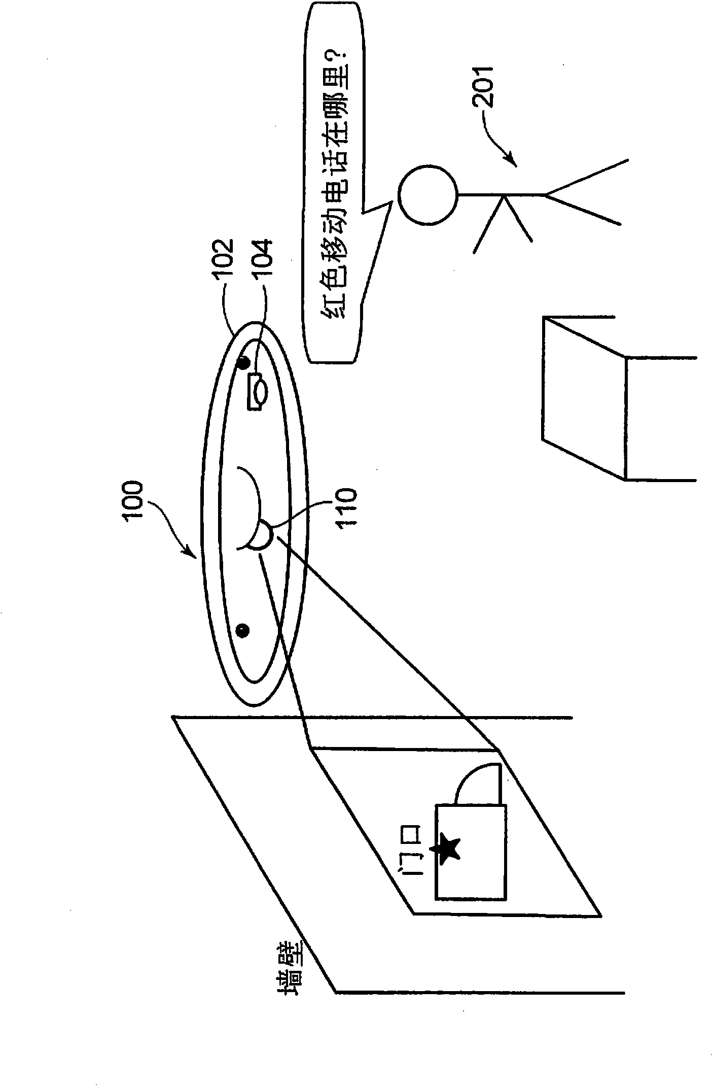
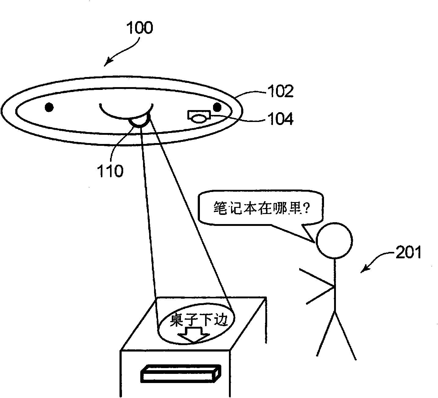
[0034] Figure 15 A schematic configuration of the light projection device 100 according to the embodiment of the present invention is shown. The light projection device 100 includes a device main body 101 , a diffused light source 102 , a voice sensor 103 , an imaging sensor 104 , a control unit 105 , a storage unit 106 , an input / output interface unit 107 , a movable projection unit 110 , and a position detection sensor 120 .
[0035] Figure 1 to Figure 3 It is a figure which shows the schematic structure and operation|movement of the light projection apparatus 100 which concerns on embodiment of this invention.
[0036] The device main body 101 of the light projection device 100 is installed, for example, on a ceiling in a room. The light projection device 100 has a movable projection unit 110 provided on the device main body 101, and can freely set a projection area indoors. In addition, the light projection device 100 can recognize the voice uttered by the pointer 201...
Embodiment approach 2
[0084] Next, light projection devices according to other embodiments of the present invention will be described below with reference to the drawings.
[0085] Figure 7 It is a schematic diagram showing the configuration and operation of the optical system of the light projection device 200 according to Embodiment 2 of the present invention. The same component numbers as those in Embodiment 1 are assigned the same component numbers, and description thereof will be omitted.
[0086] The light projection device 200 is configured such that the laser light sources 1r, 1g, and 1b are separated from the movable projection unit 91 (movable unit), and these two components are connected by a multimode fiber 61 . The red, green, and blue laser beams emitted from the laser light sources 1r, 1g, and 1b are introduced into a multimode optical fiber 61 (light guide member) and transmitted. The multimode optical fiber 61 transmits the laser light to the illumination optical system 21 insid...
Embodiment approach 3
[0098] Next, light projection devices according to other embodiments of the present invention will be described below with reference to the drawings.
[0099] Figure 8 (A) is a schematic diagram showing the configuration and operation of the optical system of the light projection device 300 according to Embodiment 3 of the present invention. The same component numbers as those in Embodiments 1 and 2 are assigned the same component numbers, and descriptions thereof are omitted.
[0100] The light projection device 300 includes a portable light projection device 310 (small light projection unit) and a movable stage stand 350 for controlling the projection direction. The portable light projection device 310 is detachable from the movable table 350 , and the portable light projection device 310 can operate as a projection device even in a separate state separated from the movable table 350 .
[0101] The movable stand 350 has a charging stand 301 for fixing the portable light p...
PUM
 Abstract
Description
Claims
Application Information
 - R&D
- Intellectual Property
- Life Sciences
- Materials
- Tech Scout
- Unparalleled Data Quality
- Higher Quality Content
- 60% Fewer Hallucinations
Browse by: Latest US Patents, China's latest patents, Technical Efficacy Thesaurus, Application Domain, Technology Topic, Popular Technical Reports.
© 2025 PatSnap. All rights reserved.Legal|Privacy policy|Modern Slavery Act Transparency Statement|Sitemap|About US| Contact US: help@patsnap.com


