
Method for first-pulse optimization in Q-switched solid-state lasers and Q-switched solid state laser

A solid-state laser and switching technology, applied in lasers, laser components, phonon exciters, etc., can solve problems such as manual optimization, different optimal parameter values, and manual intervention.

Inactive Publication Date: 2010-11-24
TRUMPF LASER MARKING SYST
View PDF1 Cites 7 Cited by
  • Summary
  • Abstract
  • Description
  • Claims
  • Application Information

AI Technical Summary

Problems solved by technology

These known methods are unsatisfactory for the following reasons: firstly, the laser operates under conditions of varying pump power, repetition rate and pulse interval ratio in use, so that manual optimization is often required or a very large amount of parameter group and select the appropriate
Second, the first pulse optimization may depend on the application, so that changes in the application require manual optimization of the control parameter set or a larger number of parameter sets must be provided
Third, the optimized parameter set is only applicable to the state at the time of optimization. When the laser Q changes later (optical instrument becomes worse, pump source degrades, HF driver degrades in the case of AOM, etc.), the optimized parameters are not valid in some cases. Refit and manual intervention required
Fourth, a different set of parameters must usually be determined individually for each tool, since optimal parameter values ​​may differ due to component differences and calibration bias between individual tools

Method used


Image

  • Method for first-pulse optimization in Q-switched solid-state lasers and Q-switched solid state laser
  • Method for first-pulse optimization in Q-switched solid-state lasers and Q-switched solid state laser
  • Method for first-pulse optimization in Q-switched solid-state lasers and Q-switched solid state laser

Examples


Embodiment Construction

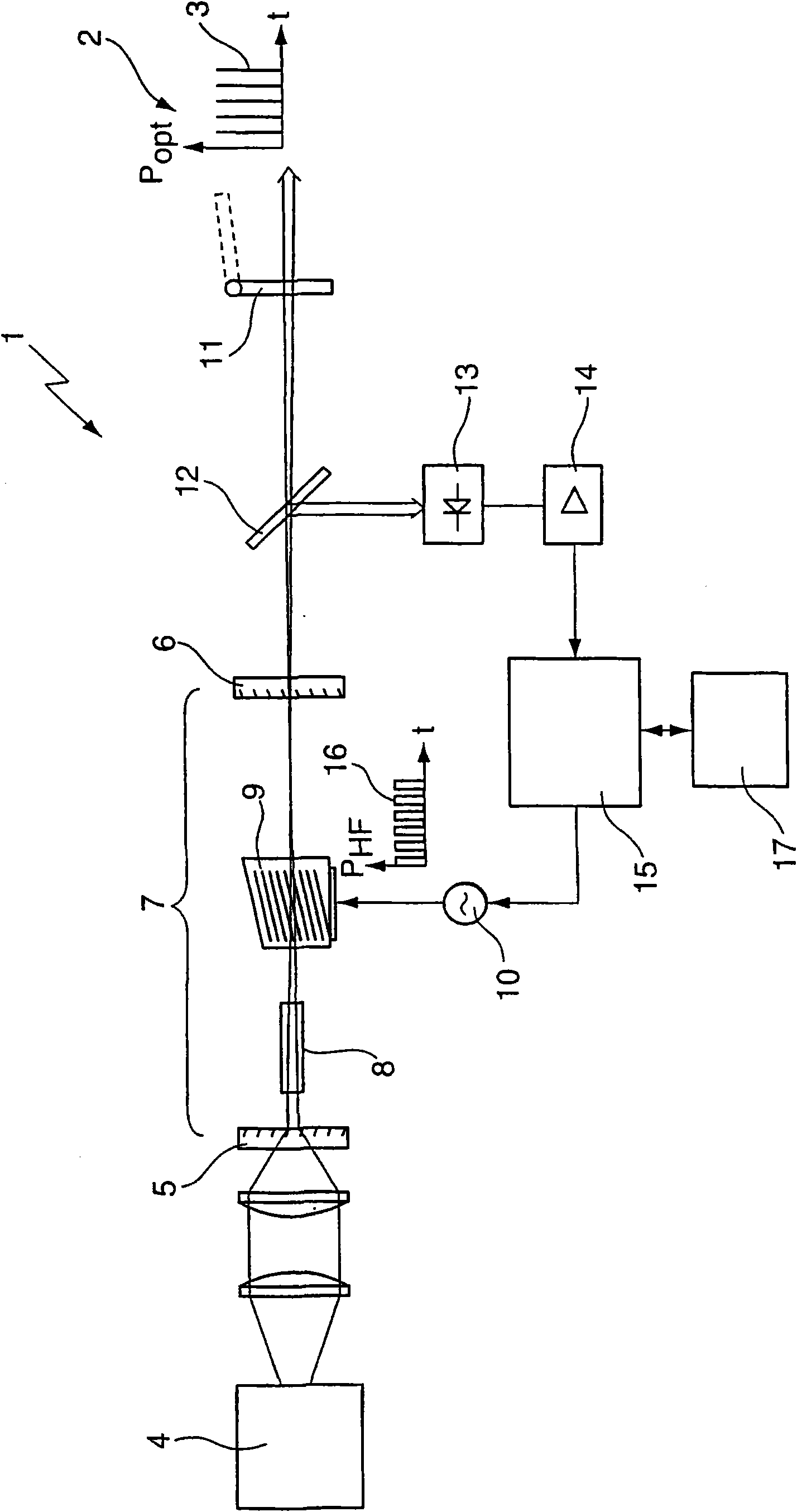
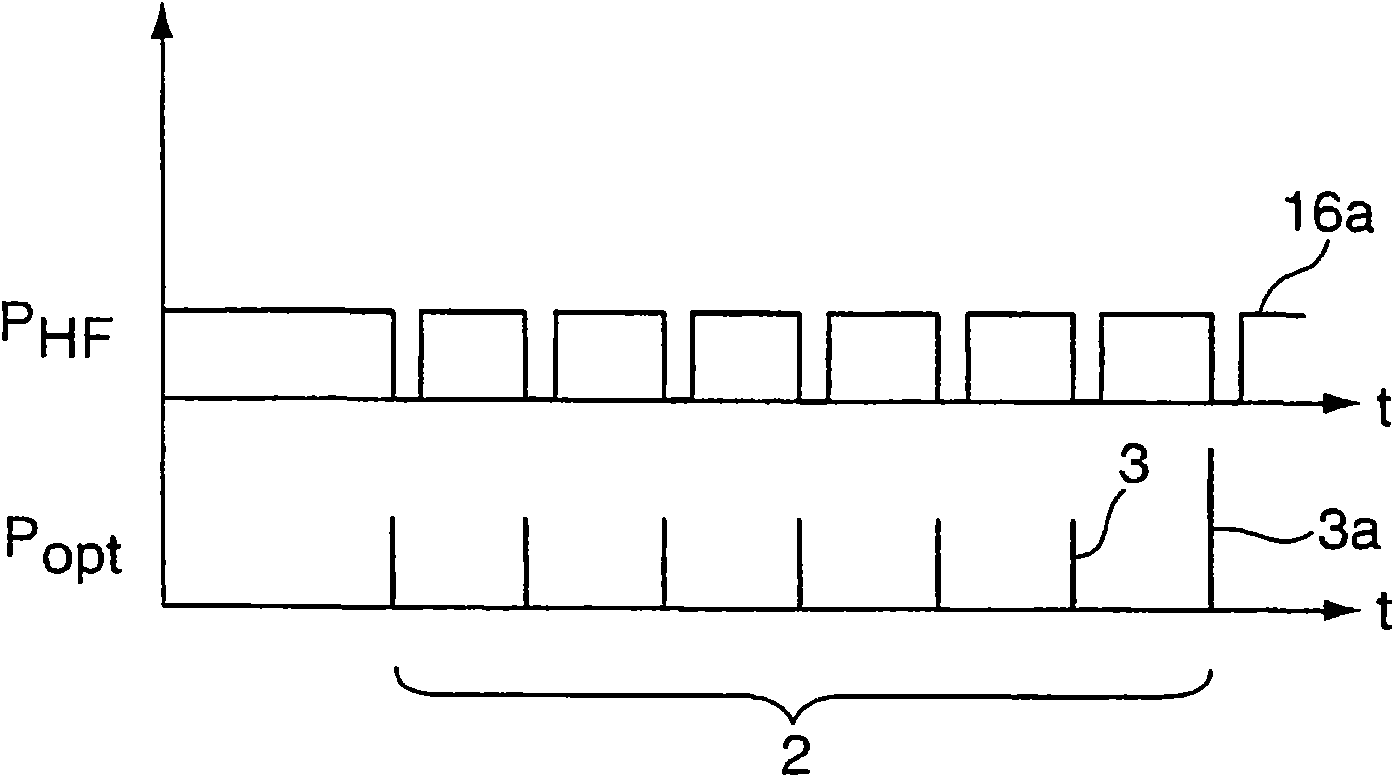
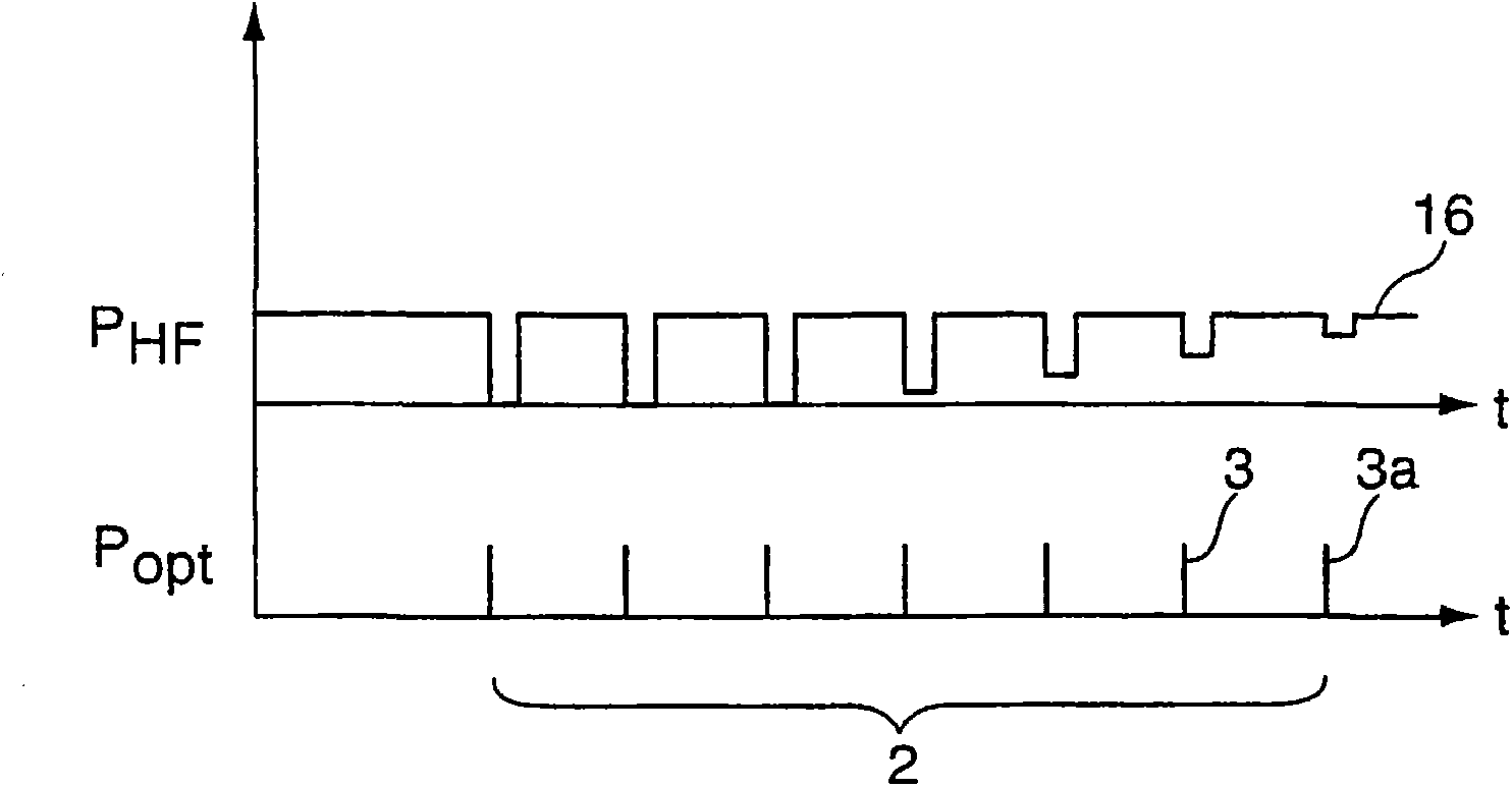
[0034] exist figure 1 The Q-switched solid-state laser 1 shown in is used to generate a pulse train 2 consisting of a number of individual pulses 3 with as constant a pulse energy as possible.

[0035] The solid-state laser 1 comprises a pump source 4, a laser resonator 7 and an HF driver 10, the laser resonator is defined by a highly reflective mirror 5 and an output coupling mirror 6 for the lasing light, in the laser resonator Housed in the cavity is a laser-active medium (laser medium) 8 pumped by a pump source 4 and an active Q-switch (Q-Switch) in the form of an acousto-optic modulator (AOM) 9 , the HF driver 10 for controlling the AOM 9 . Doped with rare earth ions (ND 3+ , Yb 3+ , Er 3+ ) base crystal (YAG, YVO 4 , YLF, GdVO 4 ) as the laser medium 8. These crystals are characterized by laser transitions with fluorescence lifetimes from tens of microseconds to milliseconds and are thus able to store in the Q-switched laser resonator 7 the energy pumped into the l...


PUM


Abstract

The invention relates to a method for generating a pulse train (2) comprising a plurality of individual pulses (3) having a desired pulse characteristic of the individual pulses (3) by means of a Q-switched solid state laser (1) having a modulator (9) for influencing the pulse characteristic of the individual pulses (3), having the following process steps: generating the individual pulses (3) of a pulse train (2) with a pulse characteristic by applying a temporal initial modulation signal (16a) to the modulator (9); detecting the pulse characteristic of the individual pulses (3) of the generated pulse train (2), generating a modified modulation signal (16) based on the detected and desired pulse characteristic and generating a pulse train (2) having a modified pulse characteristic by applying the modified modulation signal (16) to the modulator (9); repeating the last process step until a predetermined break-off criterion has been fulfilled with regard to an optimal modulation signal (16); and generating a pulse train (2) with the desired pulse characteristic of the individual pulses (3) thereof by applying the optimal modulation signal (16) to the modulator (9). The invention further relates to a Q-switched solid state laser (1) suitable for performing said method.

Description

technical field [0001] The invention relates to a method for generating a pulse train comprising a plurality of individual pulses with a desired pulse characteristic of the individual pulses by means of a Q-switched solid-state laser and a Q-switched solid-state laser suitable for carrying out the method. Background technique [0002] Pulsed Q-switched solid-state lasers are no longer considered in many areas of laser processing of materials. The main component of these processing systems is the actual laser beam source consisting of a resonator, laser active medium and Q-switch. Doped with rare earth ions (ND 3+ , Yb 3+ , Er 3+ ) base crystal (YAG, YVO 4 , YLF) as the laser active medium. These crystals are characterized by laser transitions with fluorescence lifetimes ranging from tens of microseconds to milliseconds. These crystals are thus able to store in a Q-switched laser resonator the energy pumped into the laser medium during the low-Q state. This process is ...

Claims


Application Information

Patent Timeline
Patent Type & Authority Applications(China)
IPC IPC(8): H01S3/117H01S3/136H01S3/102H01S3/131H01S3/13
CPCB23K26/063H01S3/117H01S3/1312H01S3/1306H01S3/136H01S3/1022H01S3/10069H01S3/1305B23K26/0622
Inventor H·齐莫尔D·克鲁泽
Owner TRUMPF LASER MARKING SYST
Learn More